Multi-wideband communications over multiple mediums

a multi-media, multi-channel technology, applied in the field of communication, can solve the problems of limiting the ability of devices to communicate with one another, unable to meet the needs of the home, and unable to use the phone line or coax of any apparatus,

Inactive Publication Date: 2013-03-26
GIGLE SEMICON
View PDF125 Cites 239 Cited by
  • Summary
  • Abstract
  • Description
  • Claims
  • Application Information

AI Technical Summary

Problems solved by technology

In some cases the phone line or coax in the home may be unused by any apparatus.
These device-to-device wires can become very complex, if, for example, other components such as a stereo system are also connected to the television set.
The use of a dedicated wire between devices additionally limits which devices are able to communicate with one another.
In some PLC systems, it may be difficult to pass communications through the junction box, particularly if they are on different alternating current (AC) phases.

Method used


Image

  • Multi-wideband communications over multiple mediums
  • Multi-wideband communications over multiple mediums
  • Multi-wideband communications over multiple mediums

Examples


second embodiment

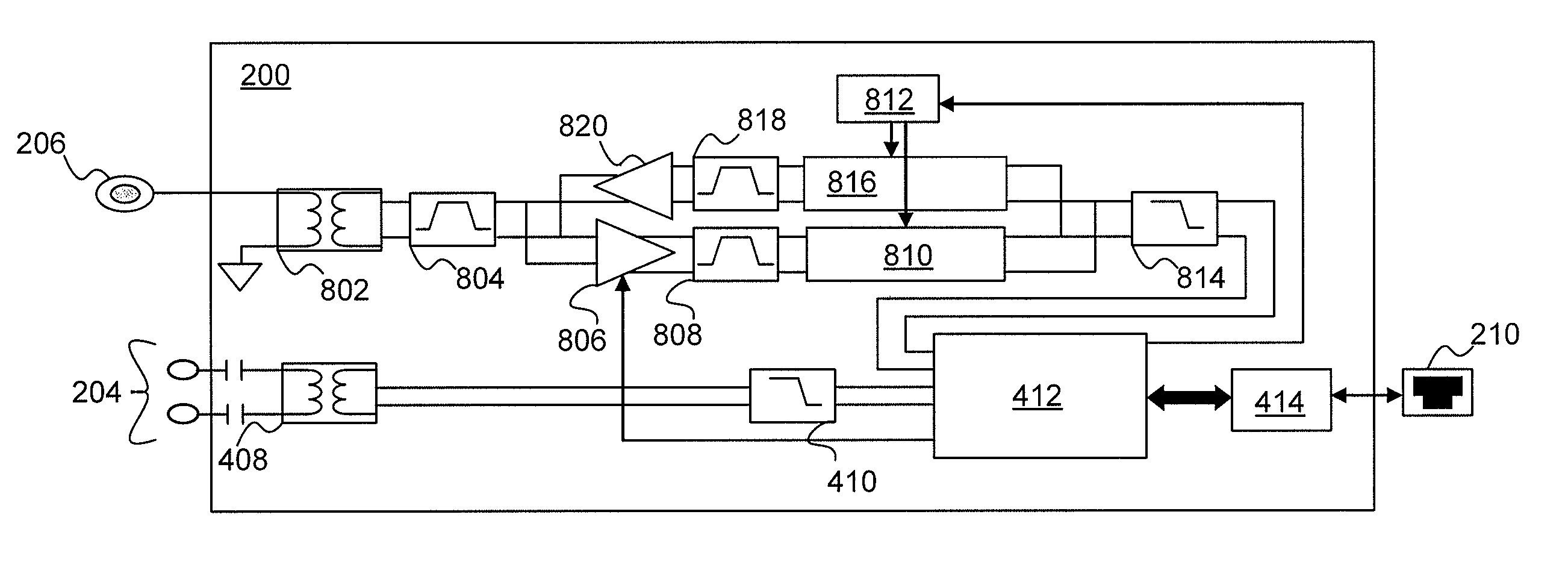
[0082]FIG. 5 is a block diagram of the multi-network interface device 200. In this embodiment, the multi-network interface device 200 is configured to communicate a first signal via the low band 304 over a powerline and to communicate a second signal via the high band 306 over a telephone line. The multi-network interface device 200 additionally comprises a second telephone line interface 208. The second telephone line interface 208 may be used to communicate voice, ADSL, VDSL, or HPNA signals within band 310.

[0083]To allow communication between the telephone line interface 202 and the second telephone line interface 208, an optional second inductive coupler 502 may be placed between the surge protector 402 and the inductive coupler 404. The second inductive coupler 502 is coupled to an optional low pass filter 504 to isolate the signal within the band 310 from other communications signals communicated within the high band 306. The low pass filter 504 may pass frequencies below appr...

third embodiment

[0084]FIG. 6 is a block diagram of a multi-network interface device 200. In this embodiment, the multi-network interface device 200 is configured to communicate a first signal via the low band 304 over a powerline, to communicate a second signal via the high band 306 over the powerline, and optionally to communicate the second signal or a third signal via the high band 306 over a telephone line. The multi-network interface device 200 comprises a second telephone interface 208 from which a fourth signal, in band 310, may be communicated as discussed in connection with FIG. 5.

[0085]The multi-network interface device 200 comprises a network processor 412 having a single high frequency AFE 416 configured to receive or transmit signals communicated via the high band 306 over both the powerline and the telephone line. The single high frequency AFE 416 optionally includes passive sharing of the powerline and the phone line. As such, the single high frequency AFE 416 can only receive or onl...

fourth embodiment

[0086]FIG. 7 is a block diagram of the multi-network interface device 200. The embodiment of multi-network interface device 200 illustrated in FIG. 7 is substantially similar to the multi-network interface device 200 illustrated in FIG. 6 except for a dual high frequency AFE 702. The dual high frequency AFE 702 includes two separate inputs configured to independently and simultaneously communicate signals in the high band 306 and through both the telephone line interface 202 and the powerline interface 204.


PUM


Abstract

A powerline communications device comprises a powerline communications interface and at least one other communications interface configured to communicate over a computing network. The powerline communications interface is further configured to receive electrical power. The computing network may comprise mediums including powerlines, telephone lines, and / or coaxial cables. In some embodiments, the powerline communications interface may communicate with a network apparatus, such as a personal computer, via an Ethernet interface. The powerline interface, the telephone line interface, and / or the coaxial cable interface may all be associated with the same media access control (MAC) address. The powerline communications device may receive a message via a first medium and repeat the message via a second medium based on a quality of service (QoS) metric. In some embodiments, the powerline communications device may communicate using multiple frequency bands.

Description

CROSS-REFERENCES[0001]This nonprovisional U.S. patent application is a continuation-in-part of nonprovisional U.S. patent application Ser. No. 11 / 536,539 filed Sep. 28, 2006 and entitled “Multi-Wideband Communications over Powerlines,” which claims benefit of and priority to European Patent Application EP 05 256 179.2, entitled “Power line Communication Device and Method,” filed Oct. 3, 2005 under 35 U.S.C. 119; a continuation-in-part of nonprovisional U.S. patent application Ser. No. 11 / 562,380 filed Nov. 21, 2006 and entitled “Network Repeater;” and a continuation-in-part of nonprovisional U.S. patent application Ser. No. 11 / 619,167 filed Jan. 2, 2007 and entitled “Unknown Destination Traffic Repetition” all of which are hereby incorporated herein by reference.BACKGROUND[0002]1. Field of Invention[0003]The present application relates generally to communications and more specifically to multi-wideband communications over multiple mediums.[0004]2. Description of the Related Art[0005...

Claims


Application Information

Patent Timeline
Patent Type & Authority Patents(United States)
IPC IPC(8): H04L12/28H04L49/111
CPCH04B3/54H04L49/30H04M11/062H04B2203/5437H04B2203/5445H04L12/2838H04B2203/5454
Inventor HURWITZ, JONATHAN EPHRAIM DAVIDRIVEIRO, JUAN CARLOSRUIZ, DAVID
Owner GIGLE SEMICON
Why Eureka
Try Eureka