Planting pot

Active Publication Date: 2013-05-07
POEPPELMANN HLDG GMBH & CO KG
View PDF15 Cites 13 Cited by
  • Summary
  • Abstract
  • Description
  • Claims
  • Application Information

AI Technical Summary

Benefits of technology

[0012]Such a plane is furthermore advantageously provided with at least two holes, which are not connected to a channel, between which a flat channel featuring a further hole for slow drainage is provided. Such an additional channel requires admittedly an additional construction effort, can however be manufactured comparatively simply because of its essentially or completely horizontally running cover layer. At the same time it supports the capillary drainage of the lower pot areas which in turn benefits the drainage of the lowest planted pot areas.
[0013]The stand area of the plant pot is preferably implemented without installation feet so that the

Problems solved by technology

The hole is however not in direct connection wit

Method used


Image

  • Planting pot
  • Planting pot
  • Planting pot

Examples


Embodiment Construction

[0022]The same of similarly effective parts are—if useful—provided with identical reference numbers. Individual technical characteristics of the following described embodiments examples can, with the characteristics of the previously described embodiment examples, lead to further improvements according to the invention.

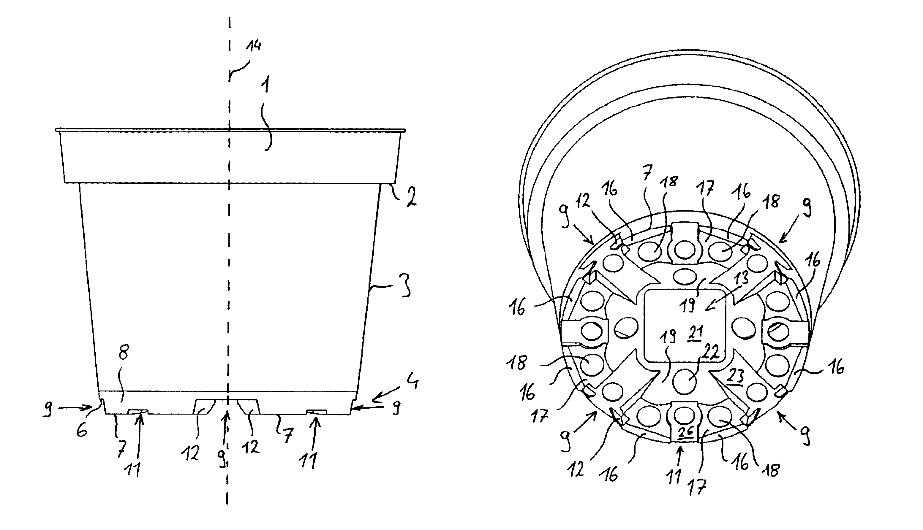
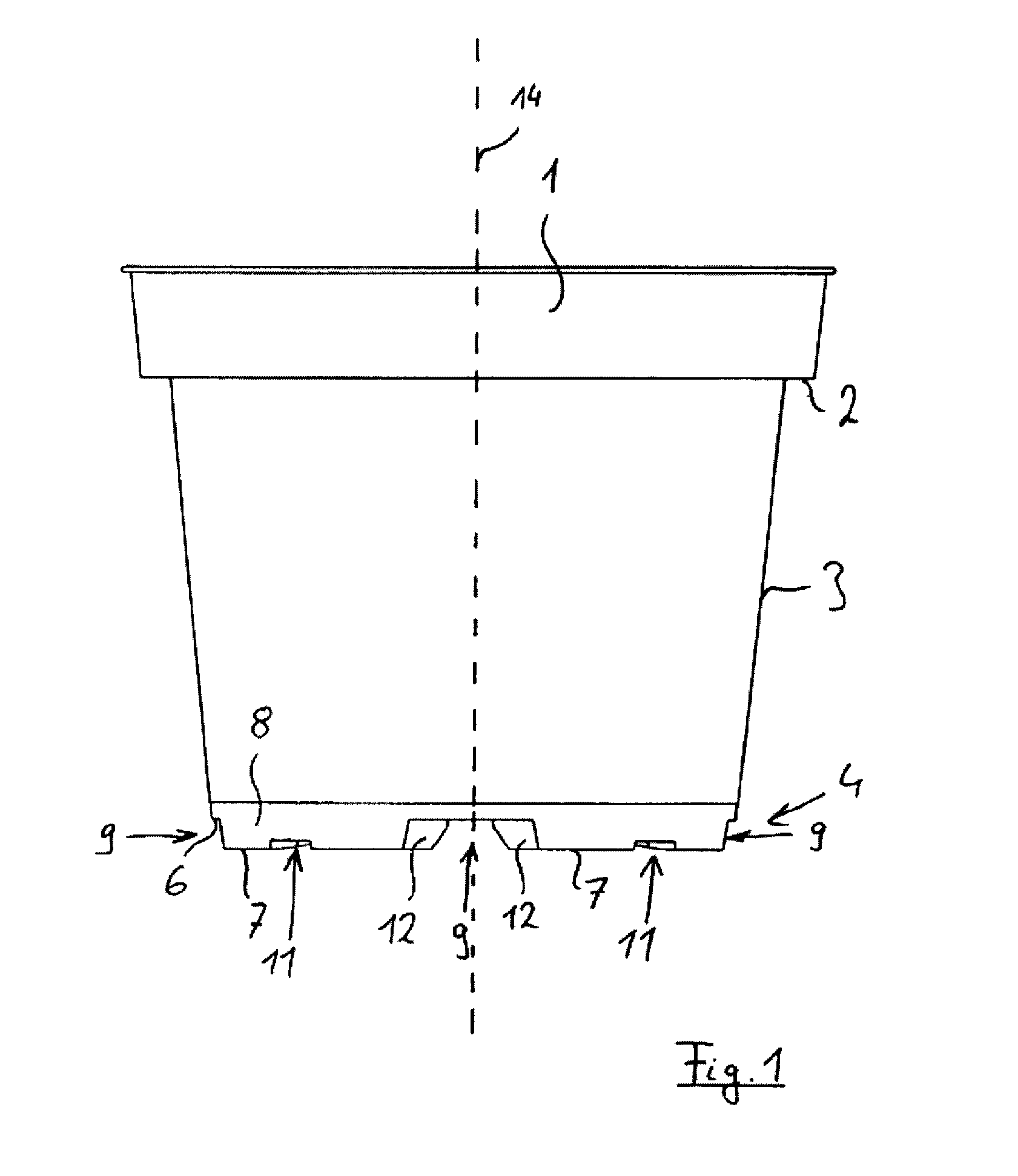
[0023]The plant pot according to the invention according to FIG. 1 encompasses an upper edge 1 that is connected by means of a projection 2 with the slightly obliquely adjusted plant pot side wall 3.

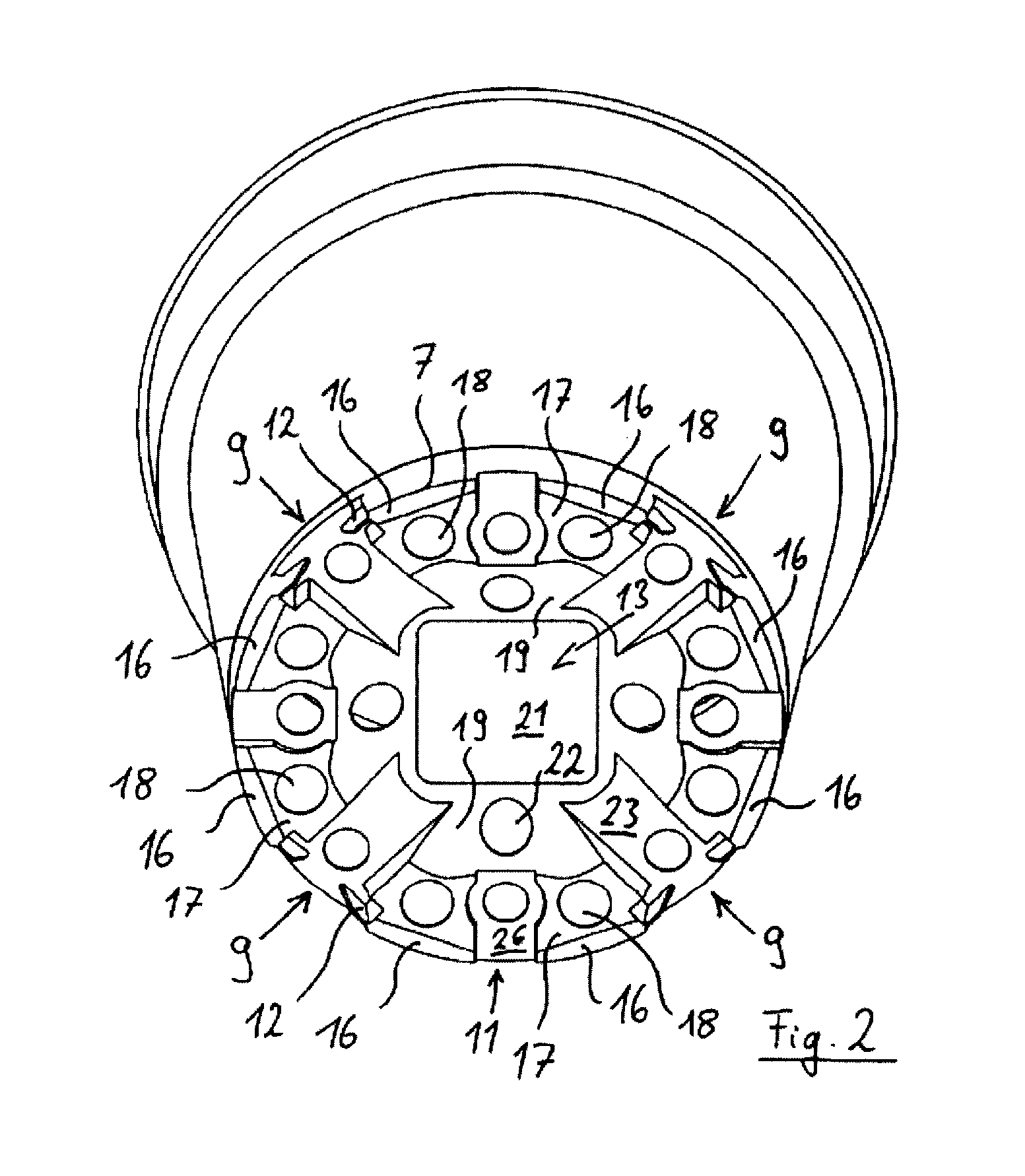
[0024]In the floor area 4 channels 9, on the left and right side of the plant pot in the figure, are identified that run across a projection 6 at right angles to a further channel 9. The floor area 4 features furthermore a lower edge 7 that is part of the stand area for the installation of the plant pot on a contact surface that is not represented. A slightly inclined, essentially vertical side wall 8 of the floor area 4 is interrupted by one of the channels 9, which exten...


PUM


Abstract

The Invention relates to a planting pot made of plastic and having a bottom provided with holes, comprising in particular a multipart base region forming a first plane for setting the planting pot on a contact surface, wherein the base region is interrupted by at least one channel leading to the outside on the edge, wherein in an area adjoining the base region the planting pot comprises a hole, which is arranged at a distance from a channel for draining a bottom planting pot region.

Description

FIELD OF THE INVENTION[0001]The invention at issue concerns a plant pot made of plastic with a floor that is provided with holes that features, implementing a first plane, in particular a multi-piece stand area for the installation of the plant pot on a contact surface, wherein the stand area is interrupted by at least one channel that extends to the edge side.BACKGROUND OF THE INVENTION[0002]In professional horticulture a plurality of plant pots with plants have to be worked on simultaneously. The watering of the plant pots takes hereby place in particular by means of low tide\high tide watering or by means of irrigation from above. For the optimal watering and draining of the plant pots as well as for the optimal ventilation of the goods located within the plant pot in particular the floor of the plant pots is provided with a larger number of channels and holes through which an exchange of air and water between the material located in the interior of the plant pot and the exterior...

Claims


Application Information

Patent Timeline
IPC IPC(8): A01G9/02
CPCA01G9/021
Inventor NOBBE, NORBERT
Owner POEPPELMANN HLDG GMBH & CO KG
Why Eureka
Try Eureka