Sheet sorting apparatus and image forming apparatus

a sorting apparatus and a technology of forming apparatus, applied in the direction of thin material handling, article delivery, function indicators, etc., can solve the problem that the stackability of sheets discharged to the second tray may sometimes decrease, and achieve the effect of preventing the decrease of the stackability of sheets

Active Publication Date: 2019-07-25
CANON KK
View PDF0 Cites 2 Cited by
  • Summary
  • Abstract
  • Description
  • Claims
  • Application Information

AI Technical Summary

Benefits of technology

[0006]The present disclosure can prevent a decrease of the stackability of sheets discharged to a second tray arranged below a first tray when the first tray is detached from a main body of an apparatus including them.

Problems solved by technology

However, in a case where the distance between the full stack detecting sensor for detecting a full stack of the first tray and the second tray is long and when sheets are discharged to the second tray until the full stack detecting sensor detects the full stack, the stackability of the sheets discharged to second tray may sometimes decrease.

Method used


Image

  • Sheet sorting apparatus and image forming apparatus
  • Sheet sorting apparatus and image forming apparatus
  • Sheet sorting apparatus and image forming apparatus

Examples


embodiment 1

Configuration of Image Forming Apparatus

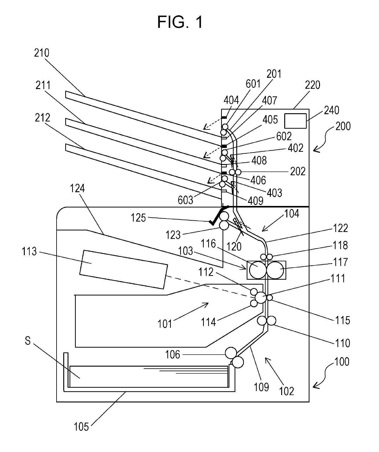
[0022]FIG. 1 illustrates a schematic structure of an image forming apparatus according to Embodiment 1 of the present disclosure. FIG. 1 illustrates a laser beam printer 100 (hereinafter, printer 100) as an image forming apparatus according to this embodiment.

[0023]As illustrated in FIG. 1, the printer 100 includes an image forming unit 101, a feed unit 102 configured to feed a sheet S (recording material) of paper, for example, to the image forming unit 101, a fixing unit 103 configured to fix an image formed on the sheet S by the image forming unit 101, and a discharge unit 104. A sheet sorting apparatus 200 is provided above the printer 100 and is configured to receive from the printer 100 and sort sheets S having images formed thereon.

[0024]The image forming unit 101 has a photosensitive drum 111 configured to rotate in counterclockwise direction in FIG. 1, a charging roller 112 configured to charge a surface of the photosensitive drum 111...

example 1

Variation Example 1

[0069]According to Embodiment 1, the CANCEL FULL STACK button 80b displayed on the operation panel 240 may be pressed by a user to cancel the fully stacked condition. However, embodiments of the present disclosure are not limited thereto.

[0070]FIG. 11 illustrates schematic structure of an image forming apparatus according to Variation Example 1. Variation Example 1 is different from Embodiment 1 in that sheet detecting sensors 430, 431, and 432 are provided. The sheet detecting sensors 430, 431, and 432 are sensors configured to detect the presence or absence of a sheet S stacked in the discharge trays 210, 211, and 212, respectively. The sheet detecting sensors 430, 431, and 432 may be photo-interrupters, for example, and are configured to output an OFF signal in a through-beam mode in which no sheet S is stacked in the respective discharge tray 210, 211, and 212 and the light beams from the photo-interrupters are not shielded. The sheet detecting sensors 430, 43...

example 2

Variation Example 2

[0074]According to Embodiment 1, a reflection type optical sensor is used as each of the full stack detecting sensors 404, 405, and 406. However, embodiments of the present disclosure are not limited thereto.

[0075]FIG. 13 illustrates a schematic structure of an image forming apparatus according to Variation Example 2. Variation Example 2 is different from Embodiment 1 in that full stack detection flags 206, 207, and 208 instead of the full stack detecting sensor 404, 405, 406, which are reflection type optical sensors, and full stack detecting sensors 414, 415, and 416 are provided.

[0076]The full stack detection flags 206, 207, and 208 are flags which move in contact with the surface of sheets S discharged to the discharge trays 210, 211, and 212, respectively. The full stack detecting sensors 414, 415, 416 are sensors (signal output units) configured to detect a full stack of the discharge trays 210, 211, and 212. The full stack detecting sensor 414, 415, 416 may...


PUM

PropertyMeasurementUnit
thresholdaaaaaaaaaa
threshold numberaaaaaaaaaa
structureaaaaaaaaaa

Abstract

A sheet sorting apparatus includes a first tray detachable from an apparatus main body, a second tray arranged below the first tray, a discharge unit to discharge a sheet to the first or second tray, a tray detecting unit to detect that the first tray is detached from the apparatus main body, a full stack detecting unit to detect a fully stacked condition of the first tray, and a control unit to control the discharge unit. In a case where the tray detecting unit detects that the first tray is detached from the apparatus main body, the control unit controls the discharge unit not to discharge a sheet to the second tray when a number of sheets discharged to the second tray reaches a threshold number of sheets, even though the full stack detecting unit does not detect the fully stacked condition.

Description

BACKGROUND OF THE INVENTIONField of the Invention[0001]The present disclosure relates to a sheet sorting apparatus and an image forming apparatus which have a plurality of discharge trays including a detachable discharge tray.Description of the Related Art[0002]Some of conventional image forming apparatuses may include a sheet sorting apparatus having a plurality of discharge trays. Such an apparatus has different discharge trays for users, for example, to sort and discharge sheets thereto, for example.[0003]Japanese Patent Laid-Open No. 2000-44105 discloses a sheet sorting apparatus having a plurality of discharge trays that is detachable from an apparatus main body of the apparatus. For example, a first tray of the plurality of discharge trays may be detached to increase a space for stacking sheets (sheet stacking space) of a second tray arranged below the first tray so that a maximum number of sheets to be stacked in the second tray can be increased.[0004]The sheet sorting appara...

Claims


Application Information

Patent Timeline
Patent Type & Authority Applications(United States)
IPC IPC(8): B65H43/06B65H29/58B65H31/24
CPCB65H43/06B65H29/58B65H31/24B65H31/02B65H43/02B65H2301/4212B65H2405/11151B65H2801/06B65H2408/111B65H2405/332B65H2511/515B65H2511/30B65H2513/42B65H43/08B65H2553/414B65H2553/61B65H2220/01B65H2220/11B65H2220/02
Inventor SATO, KAZUHISATAKAHASHI, GENKI
Owner CANON KK
Why Eureka
Try Eureka