Spray centrifugal dedusting fan

a centrifugal dedusting fan and fan motor technology, which is applied in the direction of lighting and heating apparatus, heating types, and separation processes, etc., can solve the problems of reducing the dedusting efficiency, increasing the load of the fan motor, and wasting energy, and achieves low dedusting efficiency, high energy consumption, and great air circulation resistance.

Active Publication Date: 2013-09-10
TAIAN SANYUAN VENTILATION DUST EQUIP CO LTD
View PDF3 Cites 0 Cited by
  • Summary
  • Abstract
  • Description
  • Claims
  • Application Information

AI Technical Summary

Benefits of technology

[0004]The invention provides a spray centrifugal dedusting fan, which removes dust in the air in a spray centrifugal form. The invention solves the problems of great air circulation resistance, low dedusting efficiency, high energy consumption and easy breakage of fan motor etc. in the prior art.
[0007]Beneficial effects that the invention can provide: the external wall of the centrifugal cylinder is connected to the external cylinder; an empty chamber is arranged between the centrifugal cylinder and the external cylinder, where waste water can be discharged together, thus avoiding the pollution of the parts on right part of the dedusting fan, and reducing the maintenance and prolonging service life of the dedusting fan. The trumpet-shaped first water-blocking shield is connected to the rear part inside the centrifugal cylinder; the left port diameter of the first water-blocking shield is smaller than the right port diameter; the left port of the first water-blocking shield corresponds to the centrifugal impeller and the right port corresponds to the fan. Therefore, the first water-blocking shield may prevent water from being carried away by air during the centrifugal process. This effectively avoids high moisture in discharged air, and ensures air dry after dedusting.
[0008]The lower end of the external cylinder is connected to a water seal elbow that is communicated with the empty chamber; when the fan is in use, it is hard for common discharge pipe to discharge waste water since the centrifugal cylinder is under negative pressure, and the water seal elbow can effectively seal the air flow produced by the negative pressure with the accumulated water in the return water bend, so as to ensure the discharge of waste water in the empty chamber will not be affected.
[0009]The rear part of the fan cylinder is connected to the second water-blocking shield, which is the same with the first water-blocking shield in structure, and the left port of the second water-blocking shield corresponds to the fan while the right port corresponds to the air outlet, so the second water-blocking shield can further prevent water to be carried away by air during the centrifugal process, thus avoiding high moisture in discharged air and further ensuring air dry after dedusting.
[0010]The circumferential part of the protective shell equal to hub diameter of the impeller and the left port diameter of the first and the second water-blocking shields; therefore, thus greatly reducing the resistance of following air in the dedusting fan, while saving electrical energy, promoting separating effect and further improving the dedusting efficiency.

Problems solved by technology

However, the filter may absorb more and more dust when in use and thus increasing the air circulation resistance, resulting in increasing load of the fan motor, which not only wastes energy but also decrease the de-dusting efficiency, and the fan motor becomes more liable to breakage due to constantly increasing current.
All these bring much troubles.

Method used


Image

  • Spray centrifugal dedusting fan
  • Spray centrifugal dedusting fan
  • Spray centrifugal dedusting fan

Examples


Embodiment Construction

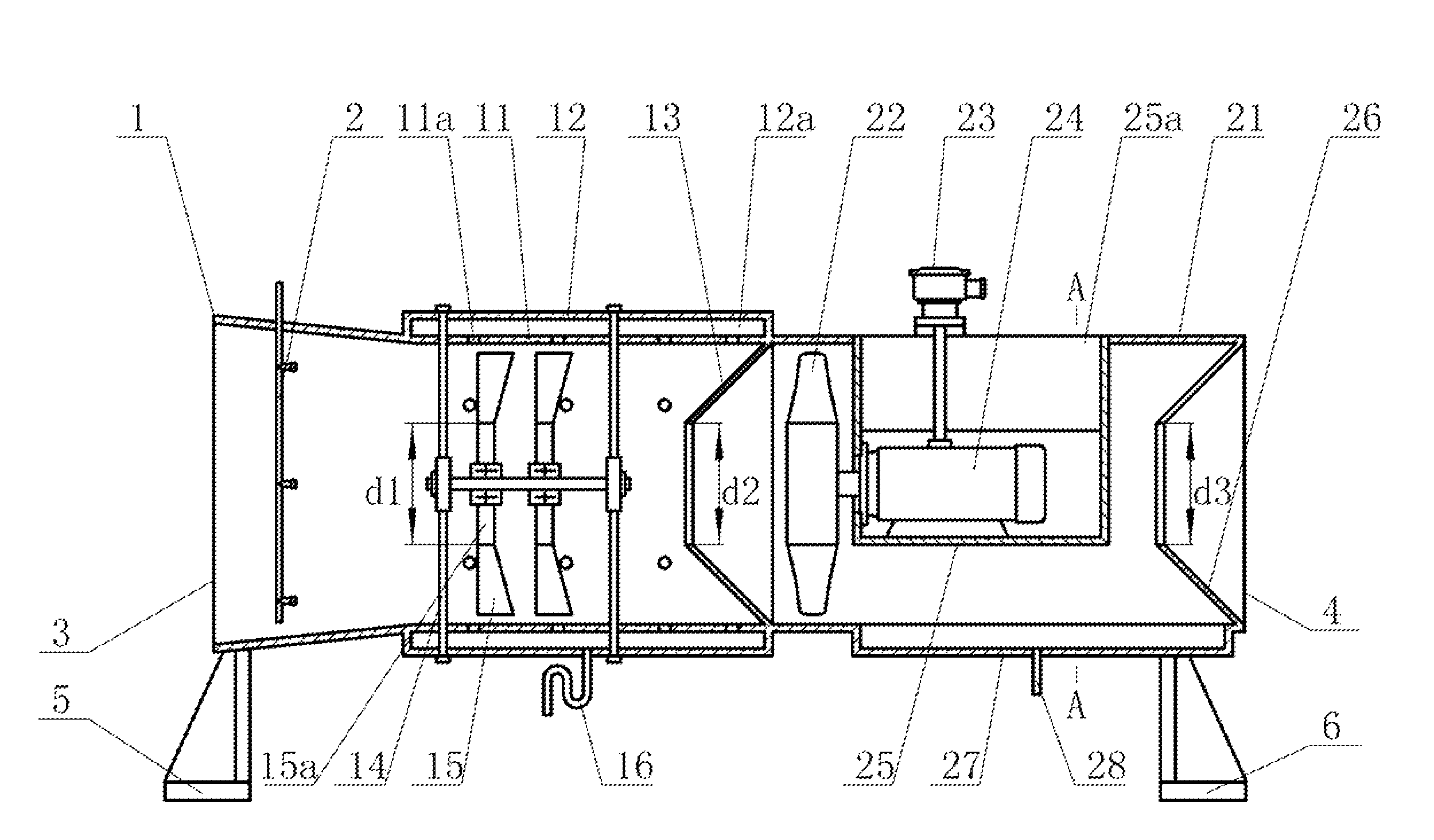
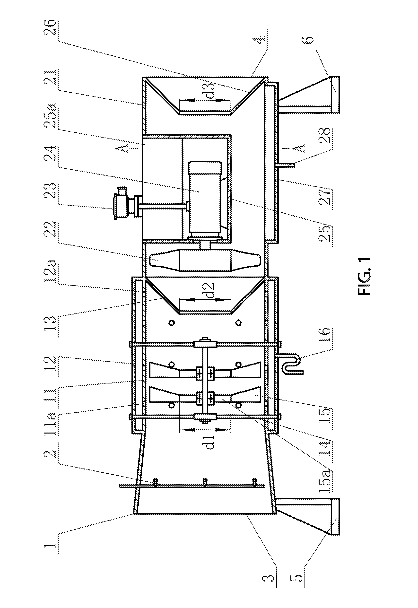
[0015]The left and right positions of the structure of this invention indicate the positions in FIG. 1. The spray centrifugal dedusting fan of the invention is in horizontal structure, with a holder set at the bottom. It shall be installed in laneway for use.

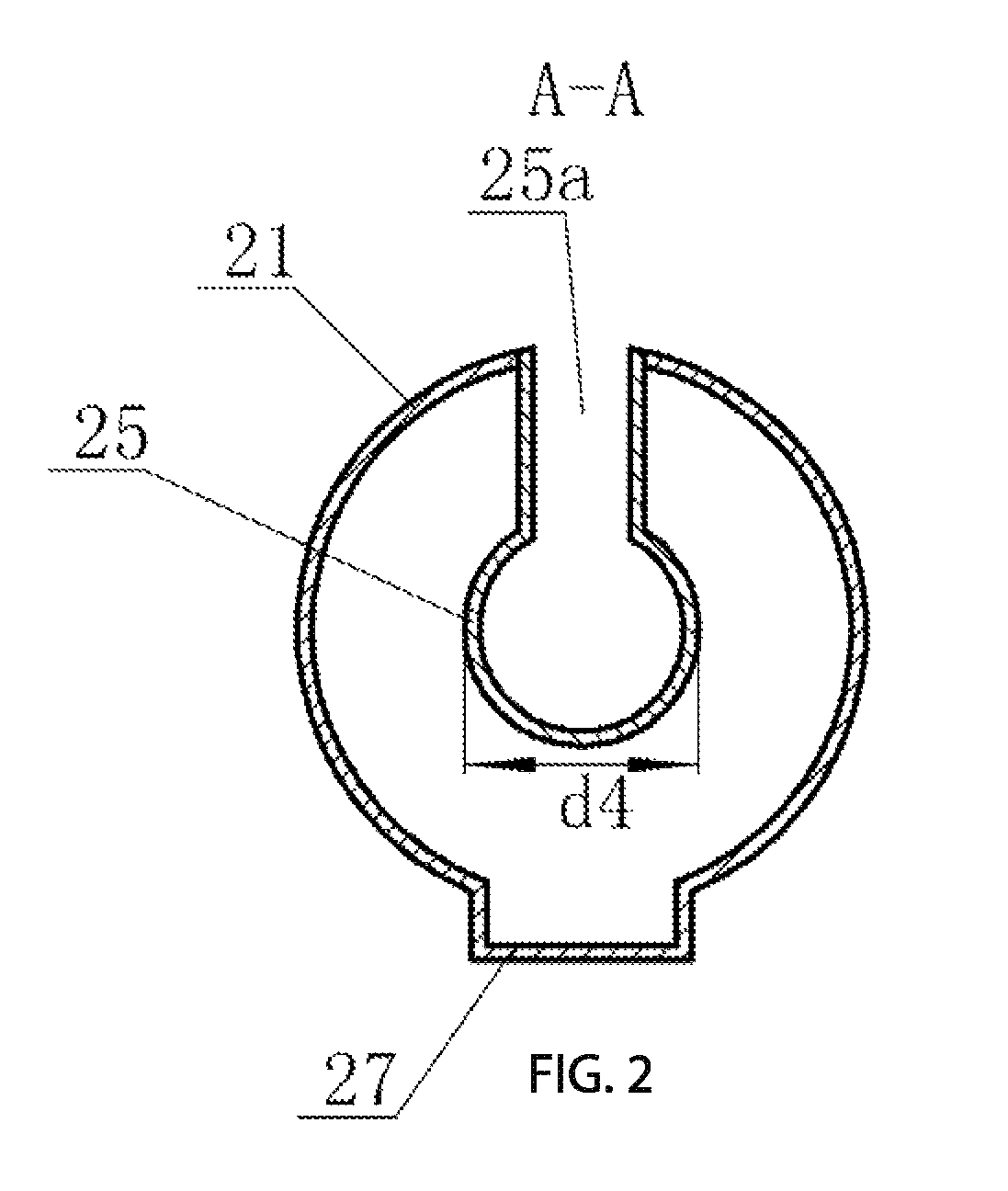
[0016]The spray centrifugal dedusting fan of the invention includes a spraying cylinder 1, a centrifugal cylinder 11 and a fan cylinder 21, which are mutually connected to form an air cylinder, and the right and left ends of the air cylinder has an air inlet 3 and air outlet 4 communicated with each other; a spraying device 2 is installed inside the spraying cylinder 1; a plurality of holes 11a are arranged on the wall of the centrifugal cylinder 11; a bracket 14 is installed inside the centrifugal cylinder 11; at least one centrifugal impeller 15 is installed on the bracket 14; the fan is installed inside the fan cylinder 21; the fan consists of a motor 24 and an impeller 22; an outer cylinder 12 is installed on the external wa...


PUM

PropertyMeasurementUnit
diameteraaaaaaaaaa
circumferential diameteraaaaaaaaaa
air circulation resistanceaaaaaaaaaa

Abstract

The invention provides a spray centrifugal dedusting fan, including an air cylinder consisting of a spray cylinder, a centrifugal cylinder and a fan cylinder; the left end and the right end of the air cylinder are respectively provided with an air inlet and an air outlet communicated with each other; a spraying device is installed in the spray cylinder; a plurality of through holes are arranged on the wall of the centrifugal cylinder; a bracket is installed inside the centrifugal cylinder; at least one centrifugal impeller is installed on the bracket; a fan is installed inside the fan cylinder; an outer cylinder is installed on the external wall of the centrifugal cylinder 11; an empty chamber is arranged between the centrifugal cylinder and the outer cylinder; the lower end of the outer cylinder is connected with a water seal elbow; the water seal elbow is communicated with the empty chamber, the trumpet-shaped first water-blocking shield is connected to the right part inside the centrifugal cylinder; the left port diameter of the first water-blocking shield is smaller than the right port in diameter; the left port of the first water-blocking shield corresponds to the centrifugal impeller and the right port corresponds to the fan. The invention adopts the spray centrifugal form to remove dust in air, which solves the problems of great air circulation resistance, low dedusting efficiency, high energy consumption and easy breakage of fan motor etc. in the prior art.

Description

CROSS REFERENCE TO RELATED PATENT APPLICATION[0001]The present application is the US national stage of PCT / CN2010 / 001569 filed on Oct. 8, 2010, which claims the priority of the Chinese patent application No. 201010137099.1 filed on Mar. 31, 2010, which application is incorporated herein by reference.FIELD OF THE INVENTION[0002]This invention relates to the technical field of dedusting equipment, more particularly, to a spray centrifugal dedusting fan that is used in mine wells to remove dust in the air of the operation environment.BACKGROUND OF THE INVENTION[0003]At present, on the sites with serious dust pollution such as operating mine wells and tunnel construction, filter-type de-dusting devices are commonly used to remove dust in the air through circulating and filtering, so as to purify the air on such working and construction sites and protect the workers' health. The de-dusting device removes dust in the air using filter with very tiny meshes. However, the filter may absorb m...

Claims


Application Information

Patent Timeline
Patent Type & Authority Patents(United States)
IPC IPC(8): B08B5/02
CPCB01D45/14B01D47/06B01D50/004E21F5/20B01D2247/104B01D2247/14B01D2221/08B01D50/40
Inventor GUO, FENGLI, TIAN
Owner TAIAN SANYUAN VENTILATION DUST EQUIP CO LTD
Why Eureka
Try Eureka