Electrical box with adjustable mounting system

a technology of mounting system and electrical box, which is applied in the direction of electrical apparatus construction details, electrical apparatus casing/cabinet/drawer, coupling device connection, etc., can solve the problem of time-consuming repositioning process, and achieve the effect of convenient repositioning of electrical box and maximum ease of repositioning electrical box

Active Publication Date: 2014-04-22
ALLIED MOLDED PRODS
View PDF14 Cites 6 Cited by
  • Summary
  • Abstract
  • Description
  • Claims
  • Application Information

AI Technical Summary

Benefits of technology

[0006]Concordant and congruous with the present invention, an electrical box assembly including a mounting system which facilitates a repositioning of the electrical box, wherein an ease of repositioning the electrical box is maximized, has surprisingly been discovered.

Problems solved by technology

Further, the repositioning process can be time consuming.

Method used


Image

  • Electrical box with adjustable mounting system
  • Electrical box with adjustable mounting system
  • Electrical box with adjustable mounting system

Examples


Embodiment Construction

[0015]The following detailed description and appended drawings describe and illustrate various exemplary embodiments of the invention. The description and drawings serve to enable one skilled in the art to make and use the invention, and are not intended to limit the scope of the invention in any manner.

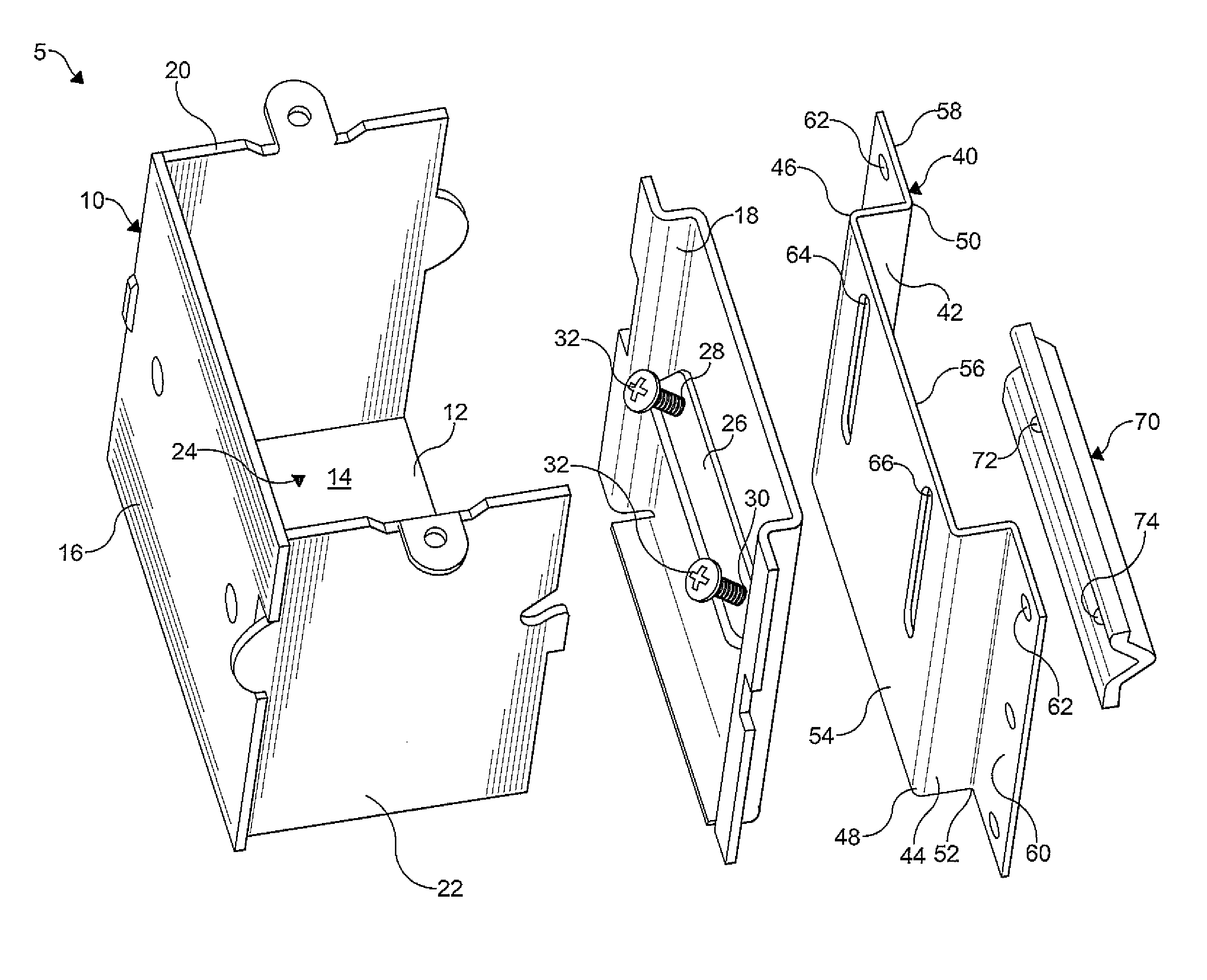
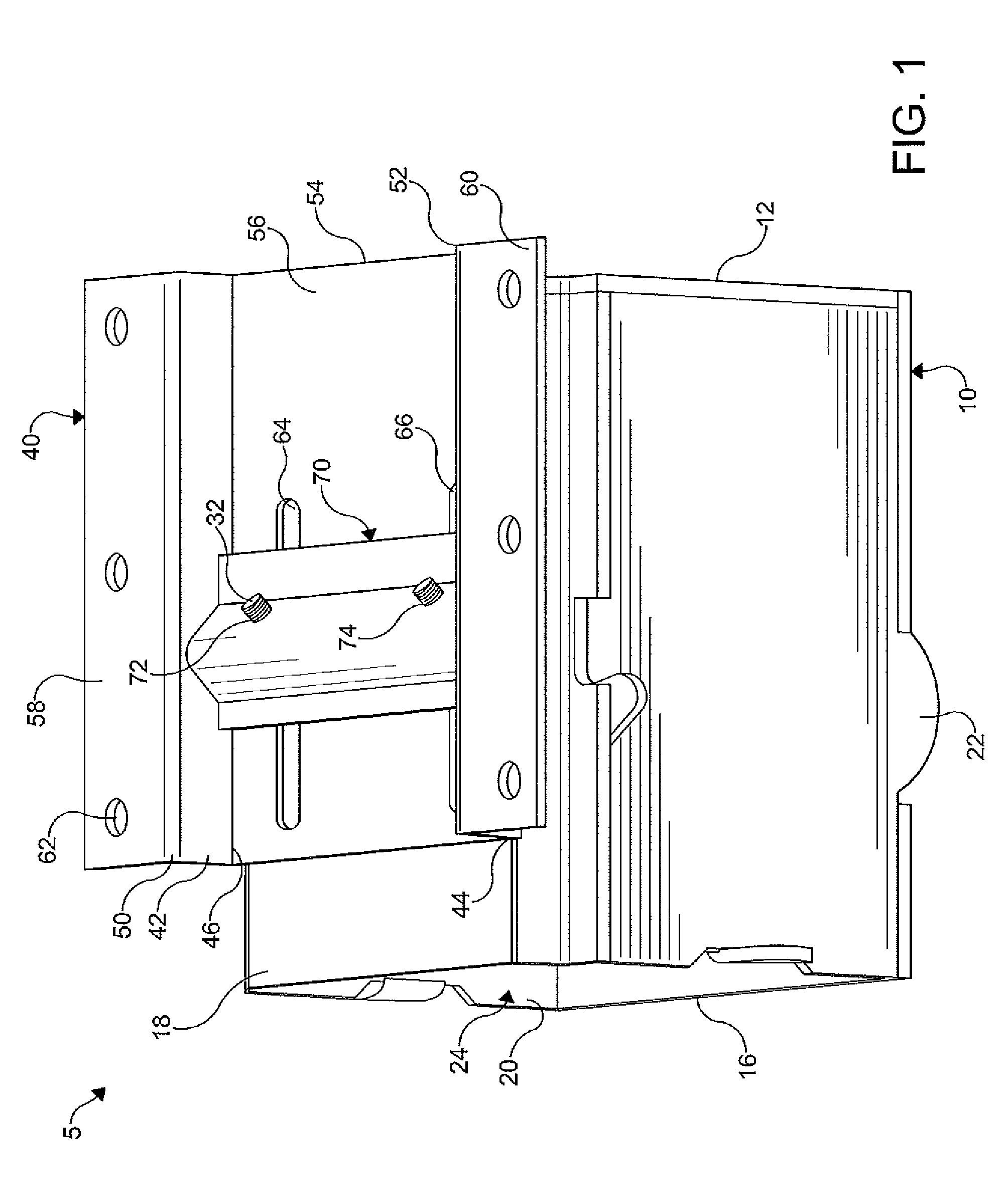
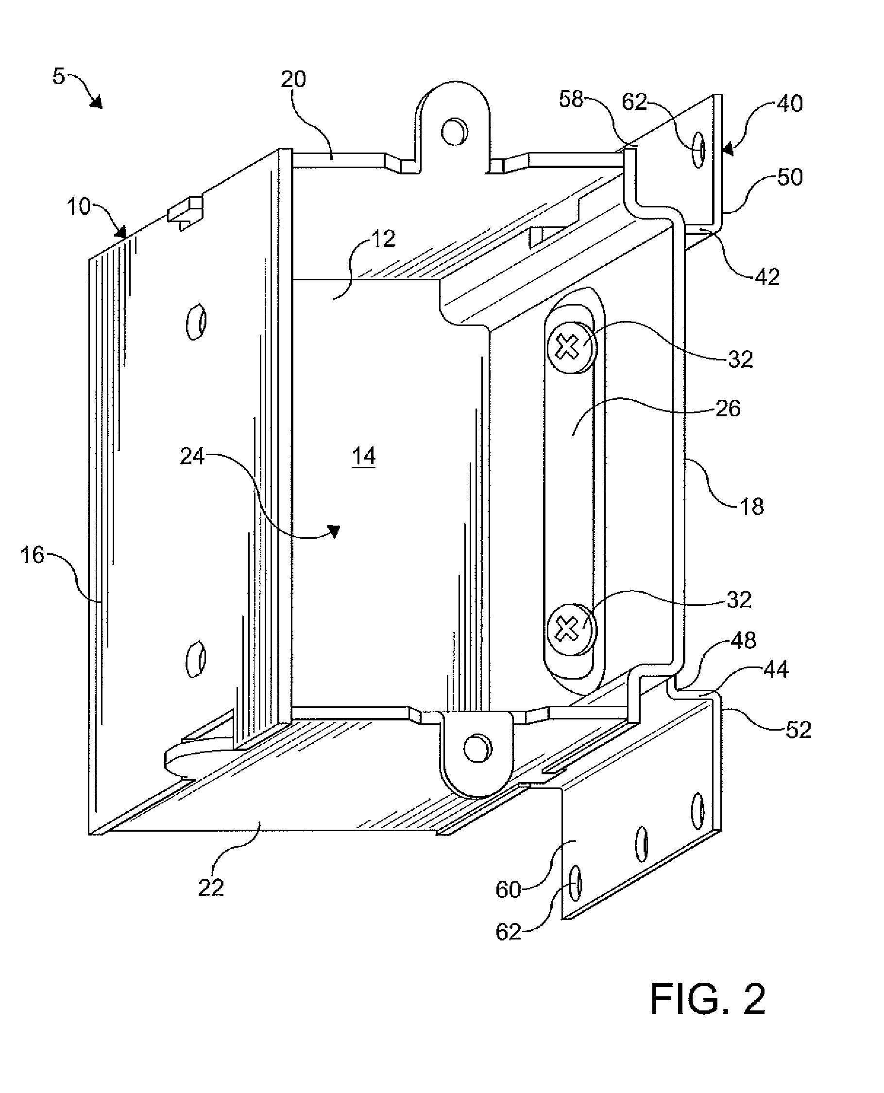
[0016]FIGS. 1-3 illustrate an electrical box assembly 5 according to an embodiment of the invention. The electrical box assembly 5 includes an electrical box 10, a removable sidewall 18 having fasteners 32 disposed therein, a mounting plate 40, and a clamp bar 70. The electrical box 10 includes a back wall 12 having an inner surface 14 and an outer surface (not shown), a pair of opposing sidewalls 16, 18, and a pair of opposing end walls 20, 22. The back wall 12, the side walls 16, 18, and the end walls 20, 22 cooperate to define a hollow interior space of the electrical box 10 having a front opening 24 permitting access to the interior space. As shown, the electrical box 10 is forme...


PUM


Abstract

An electrical box assembly is disclosed including an electrical box having at least one sidewall, the sidewall including an aperture formed therein to receive a threaded fastener. A mounting plate is provided that is attached to a support member and includes an elongate slot formed therein, wherein at least a portion of the slot is aligned with the aperture of the sidewall. A clamp bar abuts the mounting plate and has a threaded aperture formed therein, wherein the fastener extends through the aperture formed in the sidewall and the elongate slot formed in the mounting plate and is threadably received in the aperture formed in the clamp bar to movably attach the electrical box to the mounting plate.

Description

CROSS-REFERENCE TO RELATED APPLICATION[0001]This application claims the benefit of priority of U.S. Provisional Patent Application Ser. No. 61 / 261,789 filed on Nov. 17, 2009 hereby incorporated herein by reference.FIELD OF THE INVENTION[0002]The present invention relates to an electrical box assembly and more particularly to an electrical box having an adjustable mounting system that facilitates a repositioning of the electrical box.BACKGROUND OF THE INVENTION[0003]Typically, an electrical box is used to support and contain electrical devices and wiring in a centralized space. The electrical box protects the wiring and electrical devices contained therein from extrinsic conditions such rain, snow, and fire, for example. A cover plate can be provided to further protect the wiring and electrical devices and militate against accidental contact with the wiring and devices. The electrical box is typically connected to a joist, a stud, or another structural component of a building.[0004]P...

Claims


Application Information

Patent Timeline
Patent Type & Authority Patents(United States)
IPC IPC(8): H01H19/04H02G3/08H01H21/04H01H23/04H05K7/14H01H13/04H01R13/46H01H9/02H05K5/00
CPCH02G3/126
Inventor LAUKHUF, GREGG, E.
Owner ALLIED MOLDED PRODS
Why Eureka
Try Eureka