Unlock instant, AI-driven research and patent intelligence for your innovation.

Current mirror device and method

a current mirror and mirror technology, applied in the direction of differential amplifiers, amplifiers with semiconductor devices/discharge tubes, power conversion systems, etc., can solve the problems of high frequency load, low voltage supply headroom that may be unacceptable for certain low voltage applications, and conventional circuit mirror circuits that may be impractical to drive low voltage. , to achieve the effect of low power operation, low cost and reduced supply voltag

Active Publication Date: 2014-07-22
SANDISK TECH LLC
View PDF91 Cites 7 Cited by
  • Summary
  • Abstract
  • Description
  • Claims
  • Application Information

AI Technical Summary

Benefits of technology

The current mirror described in this patent is designed to have several advantages. First, it is very reliable and can function well even when the voltage level changes. Second, it allows for a stable output voltage level even when the voltage supply changes. Third, it can operate at a low voltage level, which means it can use less power and still achieve the desired results. Overall, this design can help improve the performance of high-frequency oscillators and make them more robust against changes in voltage levels.

Problems solved by technology

However, as supply voltages decrease, device operation often becomes more sensitive to fluctuations in the supply voltage.
However, a supply voltage for a second voltage domain generated by circuitry of a first voltage domain may be sensitive to fluctuations of the supply voltage of the first voltage domain.
Conventional current mirror circuits require voltage supply headroom that may be unacceptable for certain low voltage applications.
Thus, conventional circuit mirror circuits may be impractical to drive low voltage, high frequency loads.

Method used


Image

  • Current mirror device and method
  • Current mirror device and method
  • Current mirror device and method

Examples


Embodiment Construction

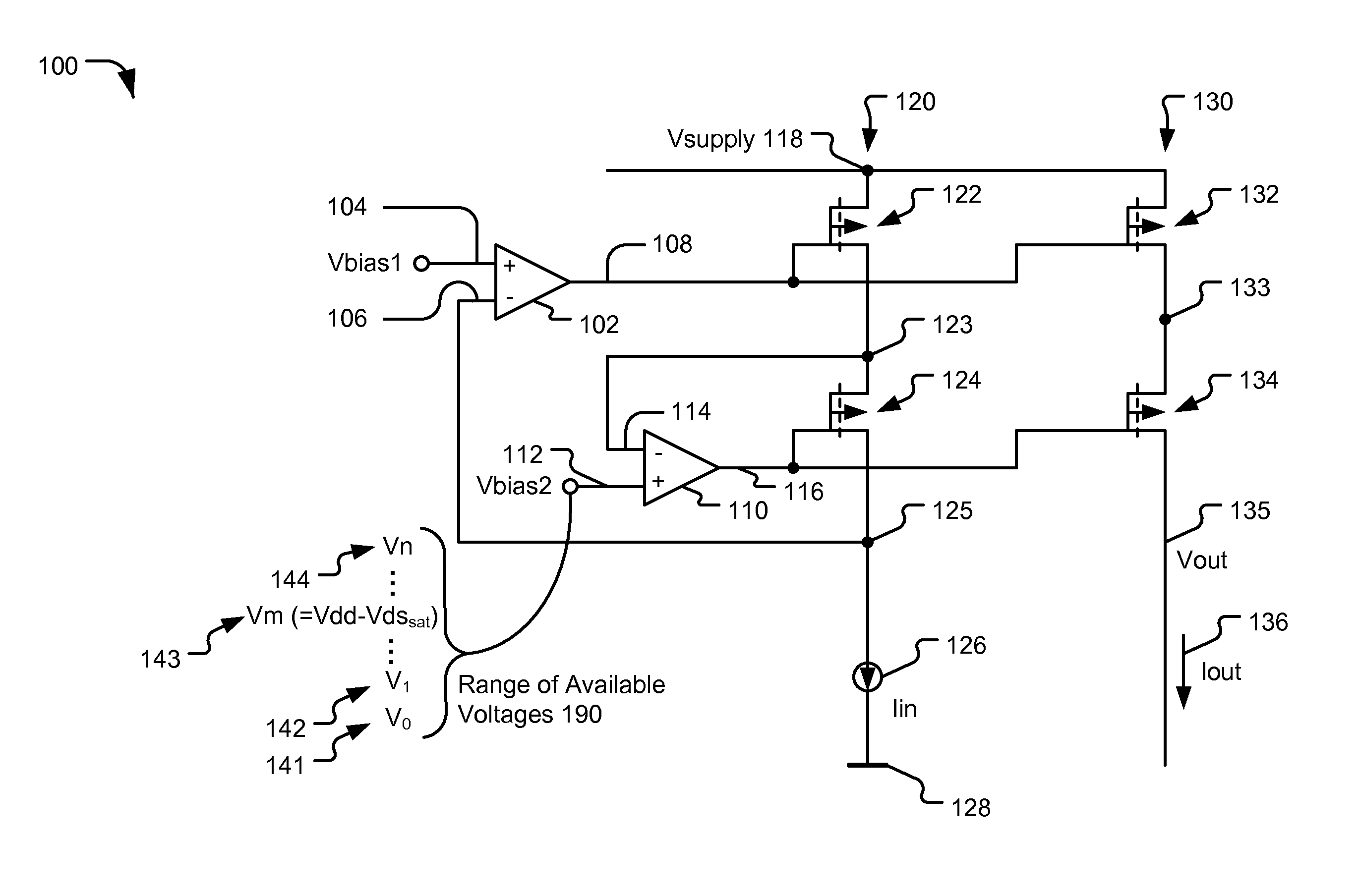
[0014]Referring to FIG. 1, a circuit device 100 is illustrated. The circuit device 100 includes a first operational amplifier 102 and a second operational amplifier 110. The circuit device 100 also includes a current mirror including a first set of transistors, such as a first pair of transistors including a first transistor 122 and a second transistor 132 and a second set of transistors, such as a second pair of transistors including a third transistor 124 and a fourth transistor 134. At least one of the transistors in the second set of transistors is in a cascode arrangement. For example, the transistor 124 or the transistor 134 or both may be in a cascode arrangement. The first operational amplifier 102 is coupled to the first transistor 122 and to the second transistor 132. The first operational amplifier 102 has a first input of a first bias voltage (Vbias1) 104 and has a second input 106 responsive to a feedback signal that is provided from a node 125 coupled to the third tran...


PUM


Abstract

In an embodiment, a circuit is disclosed that includes a current mirror including a first transistor pair and a second transistor pair. The first transistor pair includes a first transistor and a second transistor. The second transistor pair includes cascode transistors. The circuit also includes an operational amplifier having an output coupled to both the first transistor and the second transistor.

Description

I. FIELD[0001]The present disclosure is generally related to current mirror devices and methods of using current mirror devices.II. DESCRIPTION OF RELATED ART[0002]Advances in electronic device technology have resulted in smaller devices that consume less power during operation. Reduced power consumption is often a result of smaller device features and devices operating at lower supply voltages. However, as supply voltages decrease, device operation often becomes more sensitive to fluctuations in the supply voltage. In addition, some devices include multiple voltage domains to accommodate circuits that operate at different supply voltages. However, a supply voltage for a second voltage domain generated by circuitry of a first voltage domain may be sensitive to fluctuations of the supply voltage of the first voltage domain.[0003]Conventional current mirror circuits require voltage supply headroom that may be unacceptable for certain low voltage applications. In addition, the output c...

Claims


Application Information

Patent Timeline
Patent Type & Authority Patents(United States)
IPC IPC(8): G05F1/10
CPCG05F3/26
Inventor BHUIYAN, EKRAM, HOSSAIN
Owner SANDISK TECH LLC