Recording apparatus

a recording apparatus and recording technology, applied in the field of recording apparatuses, can solve the problems of increasing apparatus costs, affecting the quality of the recording, so as to prevent the formation of complicated recording apparatuses and increase the cost

Active Publication Date: 2014-10-07
SEIKO EPSON CORP
View PDF11 Cites 0 Cited by
  • Summary
  • Abstract
  • Description
  • Claims
  • Application Information

AI Technical Summary

Benefits of technology

[0007]An advantage of some aspects of the invention is that a recording apparatus including two or more paper storage portions and a supporting portion configured to support a feeding roller at a predetermined position may prevent a complicated apparatus configuration and the increase in the costs. Note that although a paper storage portion for storing sheets included in a recording apparatus is referred to by various terms, such as “cassette”, “tray”, and the like, the term “tray” is used herein.
[0009]Suppose that a configuration is employed in which the feeding roller is retracted upward in the state of the upper and lower trays being detached so that the feeding roller does not abut onto both the upper and the lower trays. In this case, as described above, a supporting portion for supporting the feeding roller at the retracted position in the state of the upper and lower trays being detached becomes necessary. Furthermore, in this case, it is necessary to provide each of the lower tray and the upper tray with a configuration for releasing the state of the feeding roller being supported at the upper position by the supporting portion. Therefore, as a result, the apparatus configuration may become complicated and the costs for the apparatus may increase.
[0010]However, according to the aspect, the feeding roller is supported at the above-described intermediate position in the state of the upper and lower trays being detached and the feeding roller may be moved from the intermediate position onto the recording medium stored in the upper tray if the recording medium is to be fed from the upper tray and may be moved from the intermediate position onto the recording medium stored in the lower tray if the recording medium is to be fed from the lower tray. Accordingly, the size of the apparatus and the costs for the apparatus may be decreased in the recording apparatus including two or more trays.
[0013]With this configuration, if the rock member is configured to displace the feeding roller by rocking around a rocking shaft, an angle formed by the rock member and the recording medium (hereinafter simply referred to as a “wedge angle”) becomes smaller in a case where a large number of recording media are stored compared to a case where a small number of recording media are stored. If the wedge angle becomes small, the force of contact between the feeding roller and the recording medium becomes small. As a result, the phenomenon of nonfeed tends to occur. However, according to the aspect, since the recording apparatus includes the pressing member configured to press the rock member toward the recording medium stored in the upper tray if a predetermined number of sheets or more are stored in the upper tray, the phenomenon of nonfeed may be prevented because the force of contact between the feeding roller and the recording medium is compensated for by the pressing member.
[0015]With the above-described configuration in which the stopper portion is configured to push aside the rock member in the course of moving the upper tray to the abutting position in the mounting direction, the increase of costs for the apparatus may be prevented because it is not necessary for the upper tray to be provided with a dedicated configuration for engaging the rock member.
[0016]Furthermore, it is preferable that, when moving the lower tray to the abutting position in the mounting direction, the lower tray be configured to release the support of the feeding roller at the intermediate position and descend the feeding roller to a position at which the feeding roller contacts the recording medium stored in the lower tray. With this configuration, the configuration for releasing the state of supporting the feeding roller at the above-described intermediate position may be provided only for the lower tray. Accordingly, the size of the apparatus and the costs for the apparatus may be decreased in the recording apparatus including two or more trays.

Problems solved by technology

As discussed in JP-A-11-139598, such configurations include a configuration in which a paper feed roller is arranged between upper and lower paper feed cassettes and the paper feed roller is shared by the upper and lower paper feed cassettes, because the size of the apparatus may become large and costs for the apparatus may increase if each of the paper feed cassettes is provided with a paper feed mechanism.
Therefore, as a result, the apparatus configuration may become complicated and the costs for the apparatus may increase.
As a result, the phenomenon of nonfeed tends to occur.

Method used


Image

  • Recording apparatus
  • Recording apparatus
  • Recording apparatus

Examples


Embodiment Construction

[0036]Hereinbelow, an exemplary embodiment of the present invention will be described with reference to the attached drawings. Note that the invention is not limited to exemplary embodiments of the invention described below. More specifically, the invention may be implemented by various modifications within the scope of the invention as defined in the claims appended hereto. An exemplary embodiment of the invention will be described based on the premise that such modifications are included in the scope of the invention.

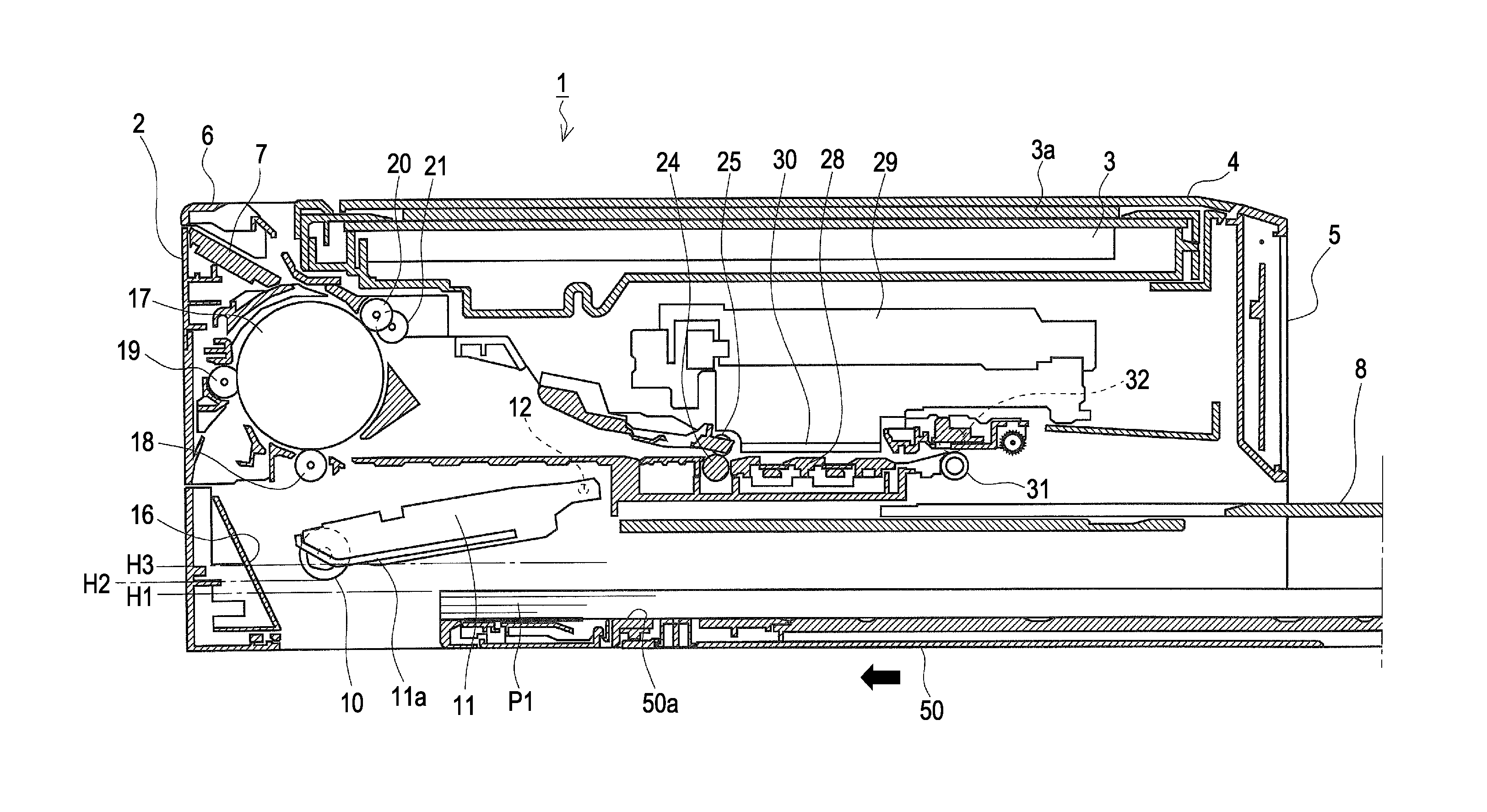
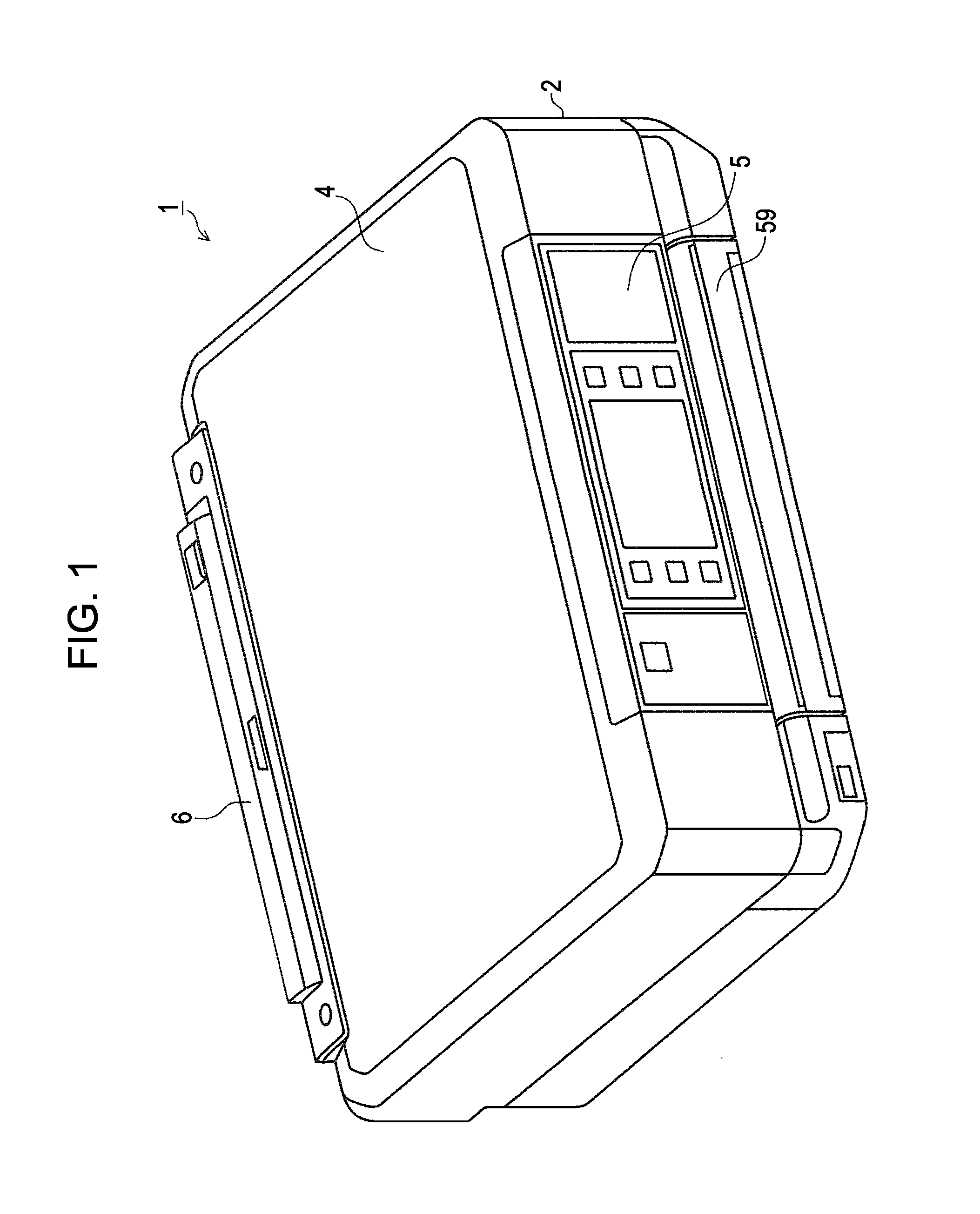
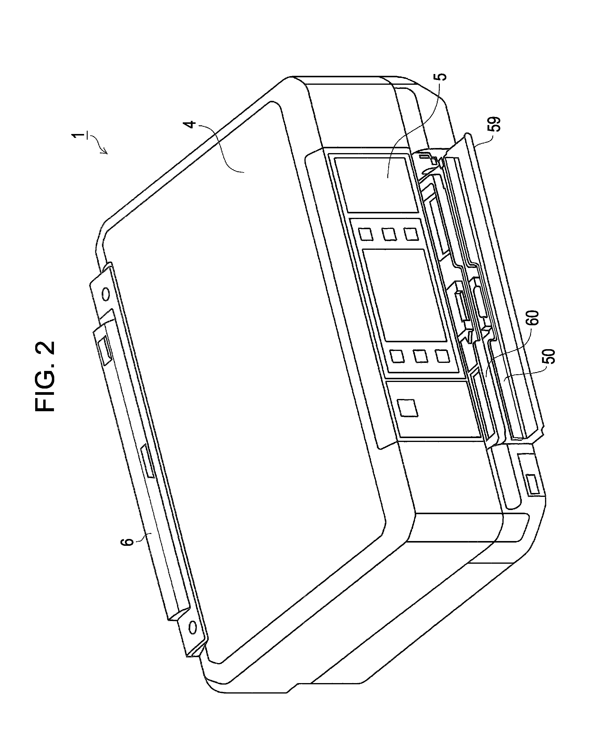
[0037]FIGS. 1 and 2 are external perspective views illustrating an ink jet printer (hereinafter simply referred to as a “printer”) 1, which is an exemplary embodiment of a “recording apparatus” according to the invention. FIG. 3 illustrates elements on larger scale on the apparatus front surface of the printer 1 in a state in which upper and lower trays are not mounted yet. FIG. 4 is a perspective view illustrating a lower tray 50. FIG. 5 is a perspective view illustr...


PUM


Abstract

A recording apparatus includes a lower tray which is detachably mounted to an apparatus body, an upper tray provided above the lower tray, which is detachably mounted to the apparatus body, and a feeding roller capable of contacting each of a recording medium stored in the lower tray and the recording medium stored in the upper tray from above. The feeding roller is supported at an intermediate position, which is lower than a position of the feeding roller reached when the feeding roller contacts a bottom surface of the upper tray and higher than a position of the feeding roller reached when the feeding roller contacts a recording medium set as a top sheet in a state in which a maximum number of recording media are stored in the lower tray, in an unmounted state of the upper tray and the lower tray.

Description

BACKGROUND[0001]1. Technical Field[0002]The present invention relates to a recording apparatus including two or more trays which are detachably mounted to an apparatus body and which store a recording medium.[0003]2. Related Art[0004]Paper feed cassettes detachably mounted to an apparatus body have been widely used. In addition, a configuration including two or more paper feed cassettes as upper and lower cassettes and capable of feeding sheets from each paper feed cassette has been widely known. As discussed in JP-A-11-139598, such configurations include a configuration in which a paper feed roller is arranged between upper and lower paper feed cassettes and the paper feed roller is shared by the upper and lower paper feed cassettes, because the size of the apparatus may become large and costs for the apparatus may increase if each of the paper feed cassettes is provided with a paper feed mechanism.[0005]In addition, as discussed in JP-A-2006-273565 and JP-A-2007-91445, there is a ...

Claims


Application Information

Patent Timeline
Patent Type & Authority Patents(United States)
IPC IPC(8): B65H3/44B65H5/26B65H1/00B65H1/26B65H3/06
CPCB65H1/00B65H3/44B65H3/0684B65H3/0669B65H1/266B65H2403/42B65H2404/133B65H2405/332B65H2405/115B65H2402/32B65H2405/3322
Inventor KOTAKA, TOSHIKAZUTAMURA, TETSUYA
Owner SEIKO EPSON CORP
Why Eureka
Try Eureka