Radio communication apparatus

a radio communication and apparatus technology, applied in the field of radio communication apparatus, can solve the problems of complicated configuration and complicated apparatus configuration, and achieve the effect of simple configuration and high diversity

Active Publication Date: 2012-04-19
RENESAS ELECTRONICS CORP
View PDF2 Cites 0 Cited by
  • Summary
  • Abstract
  • Description
  • Claims
  • Application Information

AI Technical Summary

Benefits of technology

[0009]The present inventors have found a problem that the method disclosed in Japanese Unexamined Patent Publication No. 10-210099 fails to obtain a sufficient diversity effect because it uses the signal from only one antenna. Further, it is necessary to provide a circuit for measuring the power level of the received signal in order to switch the antennas. This raises the need to place a switch, a control circuit, a measuring circuit and so on, which complicates the apparatus configuration. Particularly, because it is difficult to incorporate the branching circuit with filtering function into an LSI including the baseband processor, it is necessary to place the switch, the control circuit and so on as separate circuits. Further, it is necessary to add the control circuit and its lines in association with the transmitting / receiving circuits. This makes the configuration more complicated.
[0012]According to the exemplary aspects of an embodiment of the present invention described above, it is possible to provide a radio communication apparatus capable of achieving a high diversity effect with a simple configuration.

Problems solved by technology

The present inventors have found a problem that the method disclosed in Japanese Unexamined Patent Publication No. 10-210099 fails to obtain a sufficient diversity effect because it uses the signal from only one antenna.
This raises the need to place a switch, a control circuit, a measuring circuit and so on, which complicates the apparatus configuration.
Particularly, because it is difficult to incorporate the branching circuit with filtering function into an LSI including the baseband processor, it is necessary to place the switch, the control circuit and so on as separate circuits.
This makes the configuration more complicated.

Method used


Image

  • Radio communication apparatus
  • Radio communication apparatus
  • Radio communication apparatus

Examples


Embodiment Construction

[0022]An exemplary embodiment of the present invention is described hereinafter. The explanation provided hereinbelow merely illustrates the exemplary embodiment of the present invention, and the present invention is not limited to the below-described exemplary embodiment. The description hereinbelow is appropriately shortened and simplified to clarify the explanation. A person skilled in the art will be able to easily change, add, or modify various elements of the below-described exemplary embodiment, without departing from the scope of the present invention. In the figures, the identical reference symbols denote identical structural elements and the redundant explanation thereof is omitted.

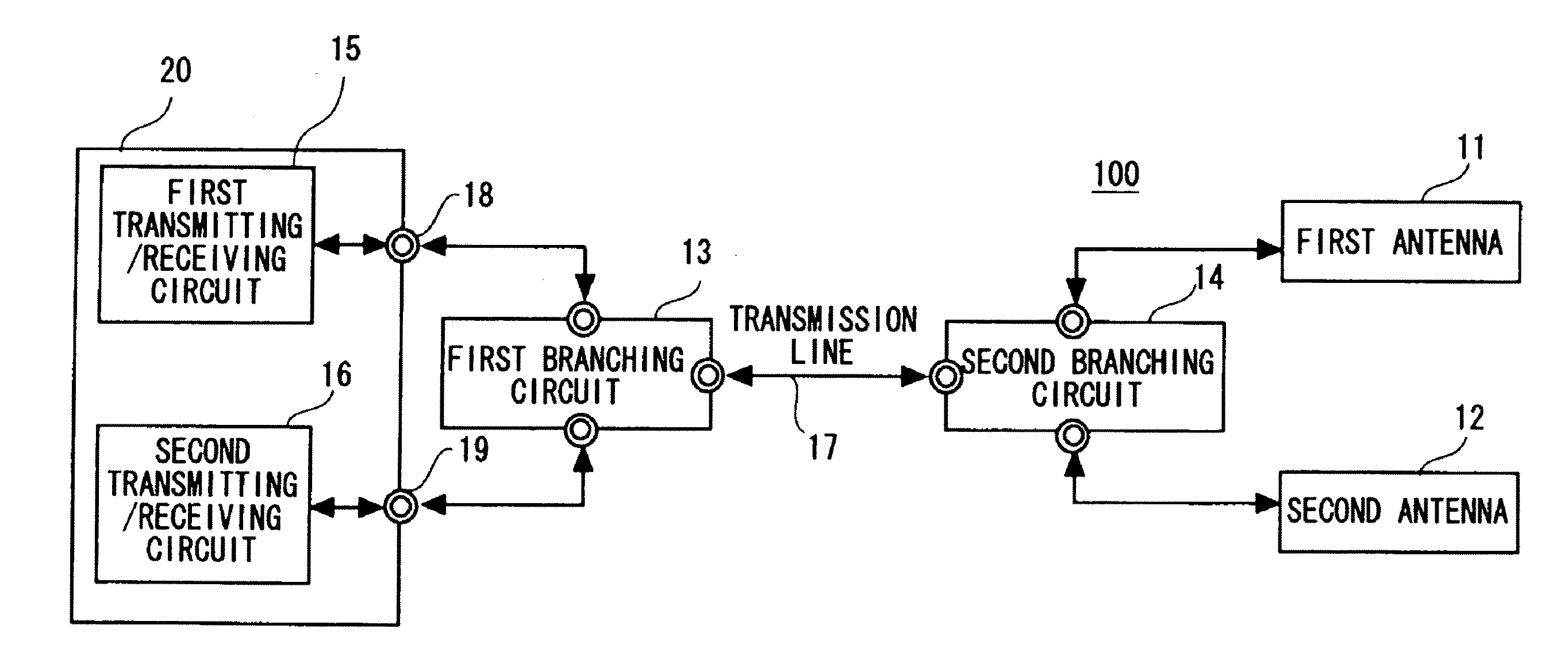
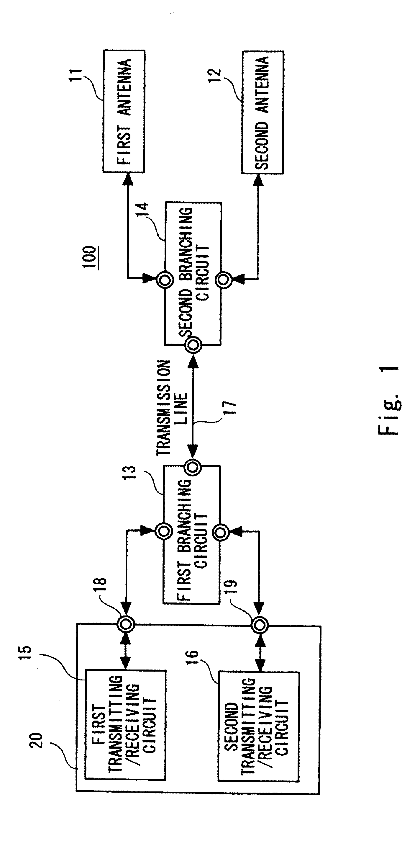
[0023]The configuration of a radio communication apparatus according to an exemplary embodiment of the present invention is described hereinafter. FIG. 1 is a block diagram showing the configuration of a radio communication apparatus according to the exemplary embodiment. A radio communication a...


PUM


Abstract

A large scale integrated (LSI) circuit includes a first terminal, a second terminal, a transmitting circuit coupled to the first terminal and the second terminal, and a receiving circuit coupled to the first terminal and the second terminal. The first and second terminals are coupled to an external portion of the large scale integrated circuit. The external portion includes a first branching circuit, a second branching circuit coupled to the first branching circuit, and first and second antennas coupled to the second branching circuit.

Description

RELATED APPLICATIONS[0001]This application is a Continuation application of U.S. patent application Ser. No. 12 / 385,838 filed on Apr. 21, 2009, which claims priority to Japanese Patent Application No. 2008-136714, filed on May 26, 2008, the entire contents of which is incorporated by reference.BACKGROUND[0002]1. Field of the Invention[0003]The present invention relates to a radio communication apparatus and, particularly, to a radio communication apparatus including a first antenna and a second antenna.[0004]2. Description of Related Art[0005]A method of processing signals in different frequency bands with use of two antennas is disclosed (United States Patent Publication No. 2005 / 0054383). In this method, signals of 5 GHz and 2.4 GHz are detected using two antennas. Then, which of the signals from the two antennas is to be used is determined according to a control signal. Further, the signals of 2.4 GHz and 5 GHz are divided by a diplexer (branching circuit with filter). The contro...

Claims


Application Information

Patent Timeline
Patent Type & Authority Applications(United States)
IPC IPC(8): H01P5/12
CPCH04B1/0057H04W52/42H04B7/12H04B7/04
Inventor SASAKI, YASUFUMIMOCHIZUKI, TAKUJI
Owner RENESAS ELECTRONICS CORP
Why Eureka
Try Eureka