
Image display apparatus and method, and driving apparatus and method

a technology of image display and driving apparatus, which is applied in the direction of instruments, color television details, projectors, etc., can solve the problems of increasing the number of parts, increasing manufacturing costs and productivity, and reducing convenience, so as to achieve the effect of efficiently measuring the modulation characteristics of the display elemen

Inactive Publication Date: 2009-11-10
SONY CORP
View PDF8 Cites 5 Cited by
  • Summary
  • Abstract
  • Description
  • Claims
  • Application Information

AI Technical Summary

Benefits of technology

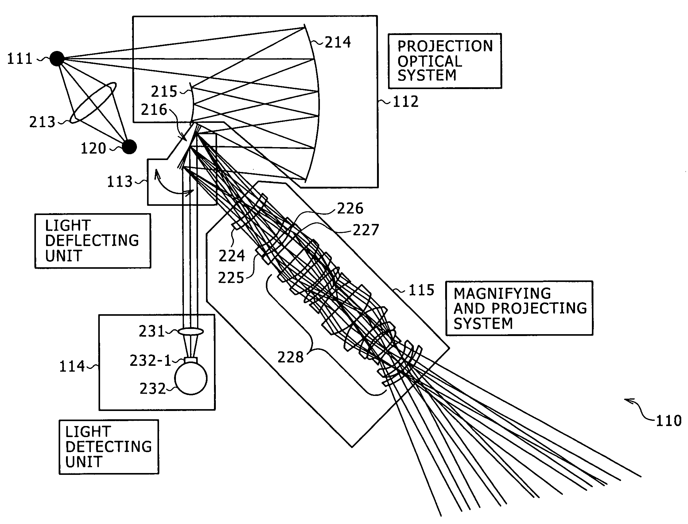
The present invention provides an image display apparatus and method that can efficiently display images and measure the modulation characteristics of the display elements. The apparatus includes a spatial light modulating element, a projection optical system, light deflecting means, and detecting means. The light deflecting means can reflect the light in one of two ranges and can be driven to change between the two ranges. The detecting means can be formed by an integrating sphere. The apparatus can also include driving means for driving the light deflecting means. The technical effects of the invention include improved image display and efficient modulation characteristics measurement.

Problems solved by technology

However, the technique according to Patent Document 2 requires the reflecting mirror 46, and therefore increases the number of parts, which may lead to an increase in manufacturing cost and a decrease in productivity.
Therefore, a place for housing the reflecting mirror 46, and the like are required, and an operation of inserting and removing the reflecting mirror, and the like is required, which may result in decreased convenience.
This complicates system configuration.
This leads to for example an increase in size and manufacturing cost of the magnifying optical system.

Method used


Image

  • Image display apparatus and method, and driving apparatus and method
  • Image display apparatus and method, and driving apparatus and method
  • Image display apparatus and method, and driving apparatus and method

Examples


Embodiment Construction

[0094]Preferred embodiments of the present invention will hereinafter be described. Correspondences between inventions described in the present specification and embodiments of the inventions are illustrated as follows. This description is to confirm that embodiments supporting the inventions described in the present specification are described in the specification. Therefore, even when there is an embodiment described in the specification but not described here, it does not mean that the embodiment does not correspond to the invention. Conversely, even when an embodiment is described here as corresponding to an invention, it does not mean that the embodiment does not correspond to inventions other than that invention.

[0095]Further, this description does not signify that all the inventions described in the specification are claimed. In other words, this description does not negate presence of inventions described in the specification but not claimed in the present application, that ...


PUM


Abstract

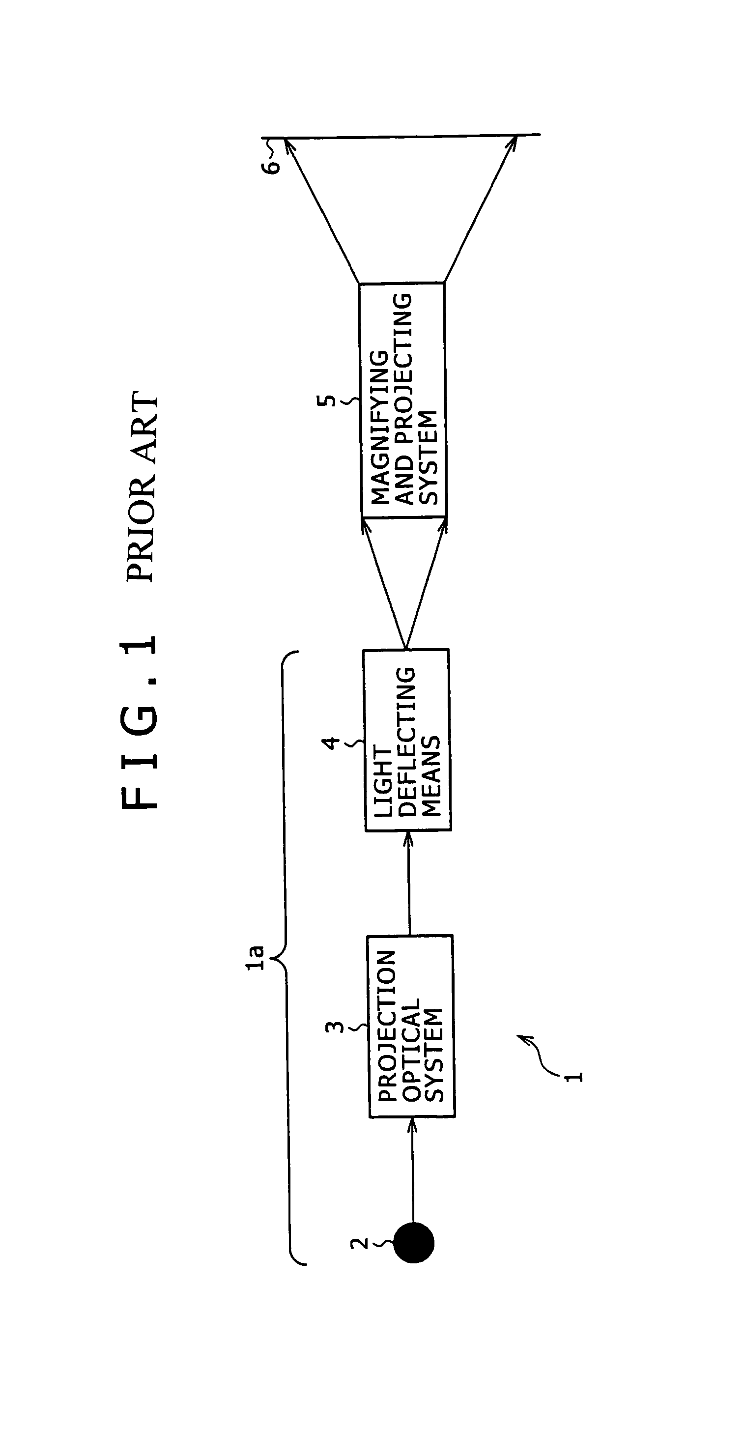
The present invention provides an image display apparatus including a spatial light modulating element formed with a plurality of light modulating elements for each modulating light from a light source and arranged in a row or a plurality of rows, a projection optical system for forming a first image on a basis of the light modulated by the spatial light modulating element, light deflecting means for forming a second image by reflecting the first image formed by the projection optical system so as to scan the first image in a direction orthogonal to a longitudinal direction of the first image, which is a longer direction of the first image, a magnifying and projecting system for magnifying the second image and projecting the second image on a screen, and detecting means for detecting intensity of the light modulated by the spatial light modulating element and reflected by the light deflecting means via the projection optical system, the detecting means being disposed at a position that the light reflected from the light deflecting means enters without passing through the magnifying and projecting system, the position being off an optical path of the light going from the light deflecting means to the magnifying and projecting system.

Description

CROSS REFERENCES TO RELATED APPLICATIONS[0001]The present invention contains subject matter related to Japanese Patent Application JP 2004-326408 filed in the Japanese Patent Office on Nov. 10, 2004, the entire contents of which being incorporated herein by reference.BACKGROUND OF THE INVENTION[0002]The present invention relates to an image display apparatus and an image display method, and a driving apparatus and a driving method, and particularly to an image display apparatus and an image display method, and a driving apparatus and a driving method that make it possible to display an image using a display element and measure the modulation characteristics of the display element efficiently.[0003]In recent years high resolution is increasingly required in for example introducing a new broadcasting system, increasing an image processing speed with an advance of an arithmetic operation device, and converting a mode in related art of projecting an image in a magnified form using a fil...

Claims


Application Information

Patent Timeline
Patent Type & Authority Patents(United States)
IPC IPC(8): G03B21/28G02B26/10
CPCH04N9/3129G03B21/28
Inventor GOTO, SATOSHIMASAKI, HIROSHIKOBAYASHI, IZUSHINISHIDA, NORIOSUZUKI, TORUSUZUKI, FUMIYASU
Owner SONY CORP
Learn More