Automatic film sticking machine

A film laminating machine and film laminating mechanism technology, applied in packaging and other fields, can solve the problems of increased labor costs, film laminating efficiency and low quality

Active Publication Date: 2017-02-22
JIANGSU BVM INTELLIGENT TECH
View PDF10 Cites 65 Cited by
  • Summary
  • Abstract
  • Description
  • Claims
  • Application Information

AI Technical Summary

Problems solved by technology

[0003] The purpose of the present invention is to overcome the problems that the existing semi-automatic film laminating machines need manual assistance, increase labor costs, and have relatively low film lamination efficiency and quality

Method used


Image

  • Automatic film sticking machine
  • Automatic film sticking machine
  • Automatic film sticking machine

Examples


Embodiment 1

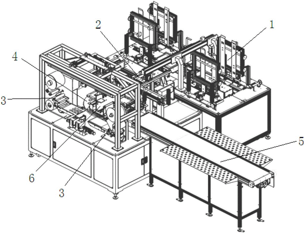
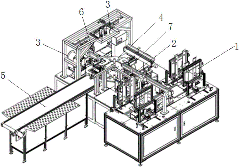
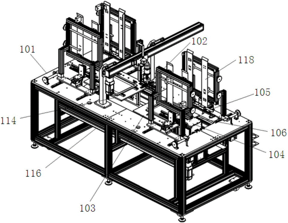
[0071] like Figure 3-5As shown, the automatic feeding mechanism 1 includes a carrier platform 101, a first tray disassembly and stacking assembly sequentially installed on the carrier platform 101, a pick-up assembly 102, and a second tray disassembly and stacking assembly. The first transfer plate 103 that performs reciprocating motion between the first tray disassembly stacking assembly and the second tray disassembly stacking assembly, where the pre-positioning mechanism 2 can cooperate with the take-up assembly 102 to complete the pre-positioning of the material;

[0072] Both the first tray splitting and stacking assembly and the second tray splitting and stacking assembly include: a tray support platform 104 that can move up and down, and a tray support platform 104 that is symmetrically arranged on both sides of the tray support platform and can move back and forth in the horizontal direction. The tray fork assembly (referred to as the first tray fork assembly 105 and ...

Embodiment 2

[0084] like Figure 5 As shown, the difference between this embodiment and Embodiment 1 is that, in this embodiment, the symmetrically arranged disk fork assemblies respectively include a moving plate 108 driven by a driving mechanism, and at least two moving plates mounted on the moving plate 108 The first forks 110 arranged at intervals (in other cases, there may also be 3, four..., may be arranged at equal intervals, or not); The mechanism drives relative movement in the horizontal direction (that is, relative movement or opposite movement in the horizontal direction), thereby driving the first fork 110 to make relative movement. The first fork 110 is a fork structure, and each fork is used to support the carrier. , and use gravity to separate the carriers.

Embodiment 3

[0086] like Figure 6 As shown, the difference between this embodiment and Embodiment 2 is that, in this embodiment, the symmetrically arranged disk fork assemblies respectively include at least two second forks 111 respectively driven by a driving mechanism (in In other cases, it can also be 3, four..., which can be arranged at equal intervals, or not); each second fork body 111 on the two symmetrically arranged disk fork assemblies is driven by the drive mechanism in the horizontal direction The second fork body 111 is a fork piece structure, each second fork body 111 is used to support the carrier tray, and the separation between the carrier trays is realized by gravity.


PUM


Abstract

The invention discloses an automatic film sticking machine. The machine comprises an automatic feeding mechanism, a pre-positioning mechanism, a film sticking automatic stripping mechanism, a film sticking station conversion mechanism, an automatic film sticking mechanism and a finished product output mechanism; according to the automatic feeding mechanism, an element to be subject to film sticking is taken out and conveyed to the pre-positioning mechanism, the pre-positioning mechanism carries out position pre-adjustment on the element to be subject to film sticking, the element to be subject to film sticking and position pre-adjustment is placed on the film sticking station conversion mechanism, the automatic film sticking mechanism enables a sticking film stripped from the film sticking automatic stripping mechanism to be pasted and covered on the element to be subject to film sticking on the film sticking station conversion mechanism, and the element subject to film sticking is output through the finished product output mechanism for quality inspection. The automatic film sticking machine can be suitable for single-layer or multi-layer rapid effective film sticking, full-automatic feeding, cleaning, sticking film stripping, sticking film absorbing and film sticking are achieved, time and labor are saved, the automatic film sticking efficiency is improved, the film sticking yield is high, and the good application prospect is achieved.

Description

technical field [0001] The invention relates to the technical field of automatic machinery, in particular to an automatic film laminating machine. Background technique [0002] In the production process of the display screen of electronic components to be filmed, it is necessary to stick a film on the surface of the screen to achieve the purpose of protection. The efficiency of manual film application is low and the effect is poor. Therefore, semi-automatic film application machines have appeared on the market, which have a low degree of automation and require manual assistance, which increases labor costs. Moreover, during the film application process, it is easy to cause creases or bubbles on the film; especially For multi-layer film (multi-layer film), air bubbles and creases are more likely to appear, and the efficiency and quality of the film are relatively low. Contents of the invention [0003] The purpose of the present invention is to overcome the problems that t...

Claims


Application Information

Patent Timeline
Patent Type & Authority Applications(China)
IPC IPC(8): B65B33/02
Inventor 李相鹏
Owner JIANGSU BVM INTELLIGENT TECH
Why Eureka
Try Eureka