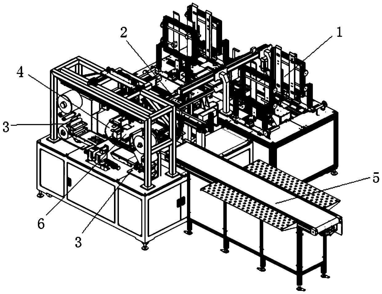
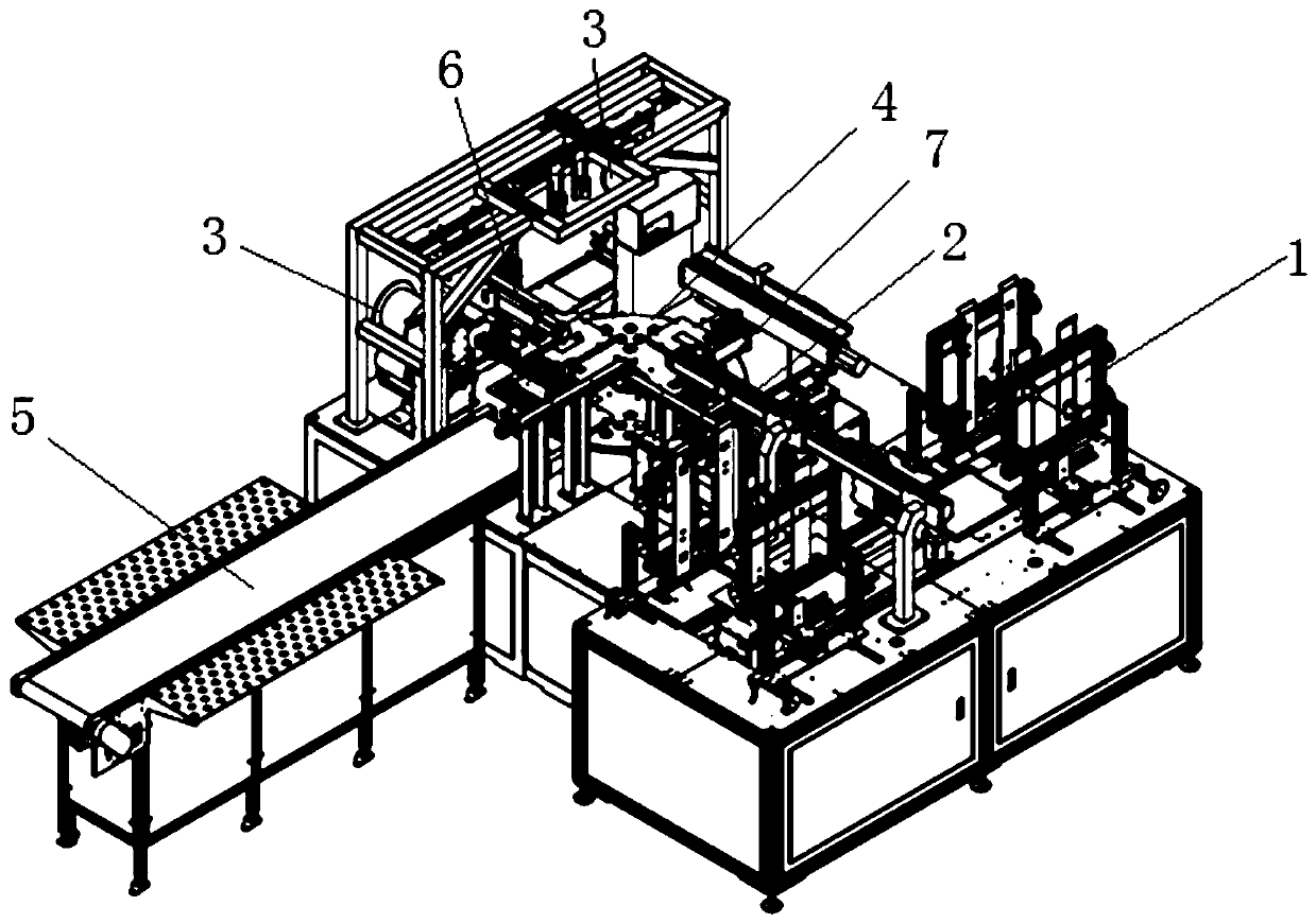
An automatic film sticking machine
A technology of laminating machine and laminating mechanism, applied in packaging and other directions, can solve the problems of increasing labor costs, laminating efficiency and low quality.
- Summary
- Abstract
- Description
- Claims
- Application Information
AI Technical Summary
Problems solved by technology
Method used
Image
Examples
Embodiment 1
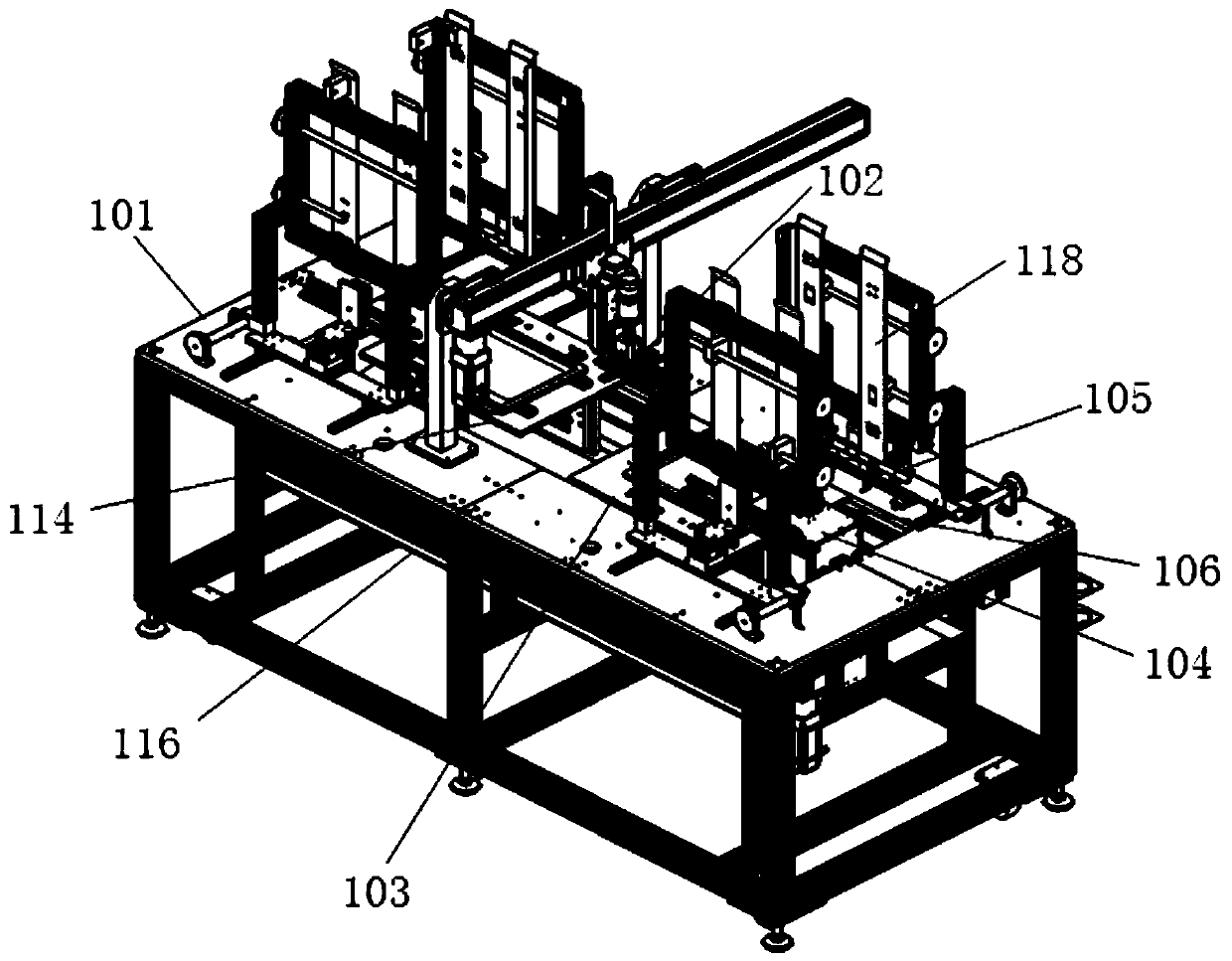
[0071] like Figure 3-5As shown, the automatic feeding mechanism 1 includes a carrier platform 101, a first tray disassembly and stacking assembly sequentially installed on the carrier platform 101, a pick-up assembly 102, and a second tray disassembly and stacking assembly. The first transfer plate 103 that performs reciprocating motion between the first tray disassembly stacking assembly and the second tray disassembly stacking assembly, where the pre-positioning mechanism 2 can cooperate with the take-up assembly 102 to complete the pre-positioning of the material;
[0072] Both the first tray splitting and stacking assembly and the second tray splitting and stacking assembly include: a tray support platform 104 that can move up and down, and a tray support platform 104 that is symmetrically arranged on both sides of the tray support platform and can move back and forth in the horizontal direction. The tray fork assembly (referred to as the first tray fork assembly 105 and ...
Embodiment 2
[0084] like Figure 5 As shown, the difference between this embodiment and Embodiment 1 is that, in this embodiment, the symmetrically arranged disk fork assemblies respectively include a moving plate 108 driven by a driving mechanism, and at least two moving plates mounted on the moving plate 108 The first forks 110 arranged at intervals (in other cases, there may also be 3, four..., may be arranged at equal intervals, or not); The mechanism drives relative movement in the horizontal direction (that is, relative movement or opposite movement in the horizontal direction), thereby driving the first fork 110 to make relative movement. The first fork 110 is a fork structure, and each fork is used to support the carrier. , and use gravity to separate the carriers.
Embodiment 3
[0086] like Image 6 As shown, the difference between this embodiment and Embodiment 2 is that, in this embodiment, the symmetrically arranged disk fork assemblies respectively include at least two second forks 111 respectively driven by a driving mechanism (in In other cases, it can also be 3, four..., which can be arranged at equal intervals, or not); each second fork body 111 on the two symmetrically arranged disk fork assemblies is driven by the drive mechanism in the horizontal direction The second fork body 111 is a fork piece structure, each second fork body 111 is used to support the carrier tray, and the separation between the carrier trays is realized by gravity.
PUM
 Abstract
Description
Claims
Application Information
 - R&D
- Intellectual Property
- Life Sciences
- Materials
- Tech Scout
- Unparalleled Data Quality
- Higher Quality Content
- 60% Fewer Hallucinations
Browse by: Latest US Patents, China's latest patents, Technical Efficacy Thesaurus, Application Domain, Technology Topic, Popular Technical Reports.
© 2025 PatSnap. All rights reserved.Legal|Privacy policy|Modern Slavery Act Transparency Statement|Sitemap|About US| Contact US: help@patsnap.com


