Dielectric antenna and fill level sensor using the radar principle

a technology of fill level sensor and dielectric antenna, which is applied in the direction of waveguide horn, machine/engine, instruments, etc., can solve the problems of disturbance in measuring fill level, difficult to determine fill level, and high construction complexity

Inactive Publication Date: 2014-11-11
KROHNE MESSTECHNICK GMBH & CO KG
View PDF25 Cites 220 Cited by
  • Summary
  • Abstract
  • Description
  • Claims
  • Application Information

AI Technical Summary

Benefits of technology

[0015]Thus, the object of the invention is to provide a dielectric antenna and a fill level sensor having such an antenna that makes it possible to measure the surface of a medium with an essentially consistent measuring accuracy.
[0034]Alternatively, a horn antenna is used as supply element. In order to shorten the geometric length of the antenna in one variation, only the last part of the horn antenna is used, whose excitation occurs in such a manner that the same phase front is created at the end of the horn as when using the normal horn length. A further alternative uses patch antennae, which, for example, are mounted directly on the inner component. One advantage of the patch antennae is the reduction of size of the antenna. A further variation involves using a filament conductor made of a suitable dielectric medium as the supply element.

Problems solved by technology

In particular, in the case of bulk materials, difficulties can arise in determining the fill level due to the occurrence of material cones.
Objects, such as, e.g., a stirring device, can be further found in the container in any type of medium, these objects reflect the radar waves and cause disturbance in measuring the fill level.
Due to the number of antennae, construction is very complex.
However, this is disadvantageous in that the radiation patterns are impaired by the shifting of the direction of radiation.
Mostly, problems include the large amount of effort or space requirements or non-consistent measurement accuracy in all measured spatial areas.

Method used


Image

  • Dielectric antenna and fill level sensor using the radar principle
  • Dielectric antenna and fill level sensor using the radar principle
  • Dielectric antenna and fill level sensor using the radar principle

Examples


Embodiment Construction

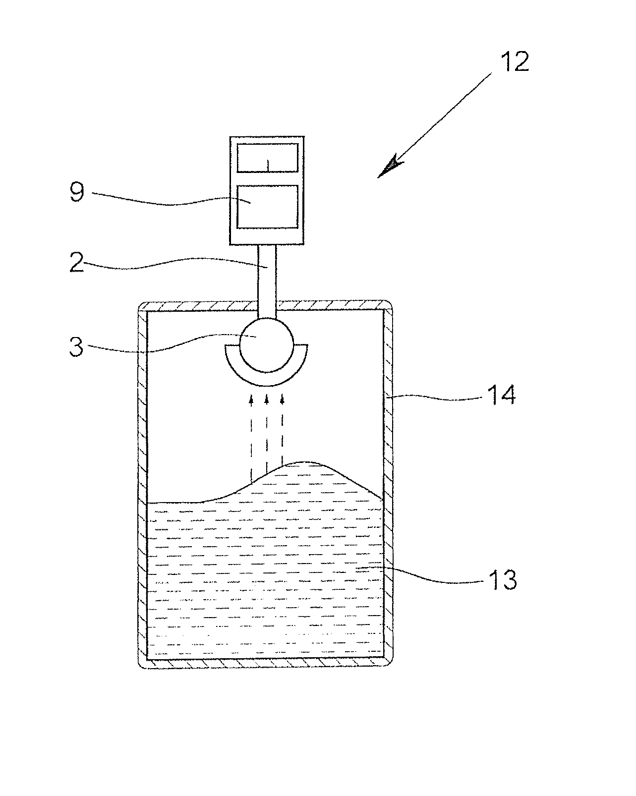
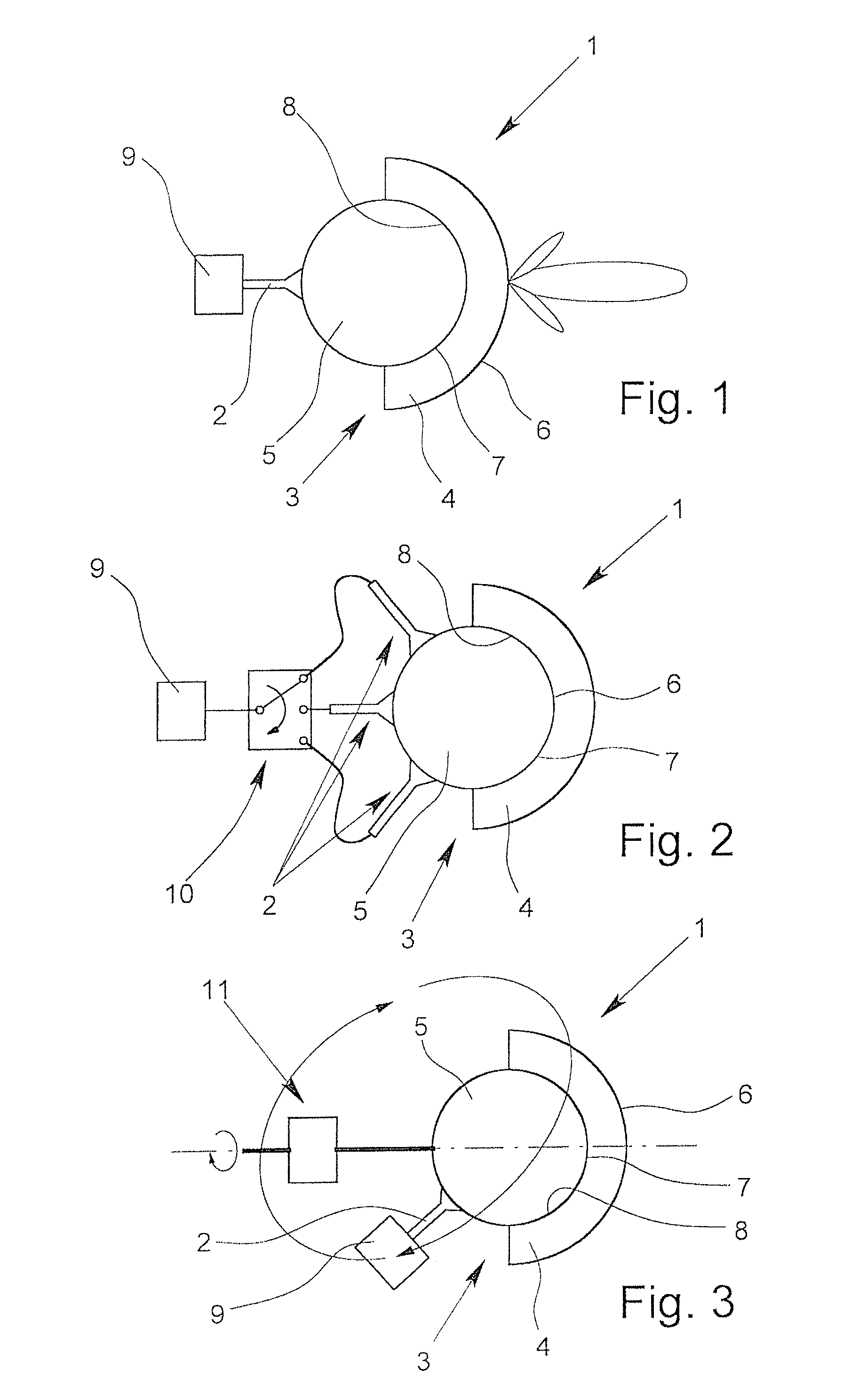
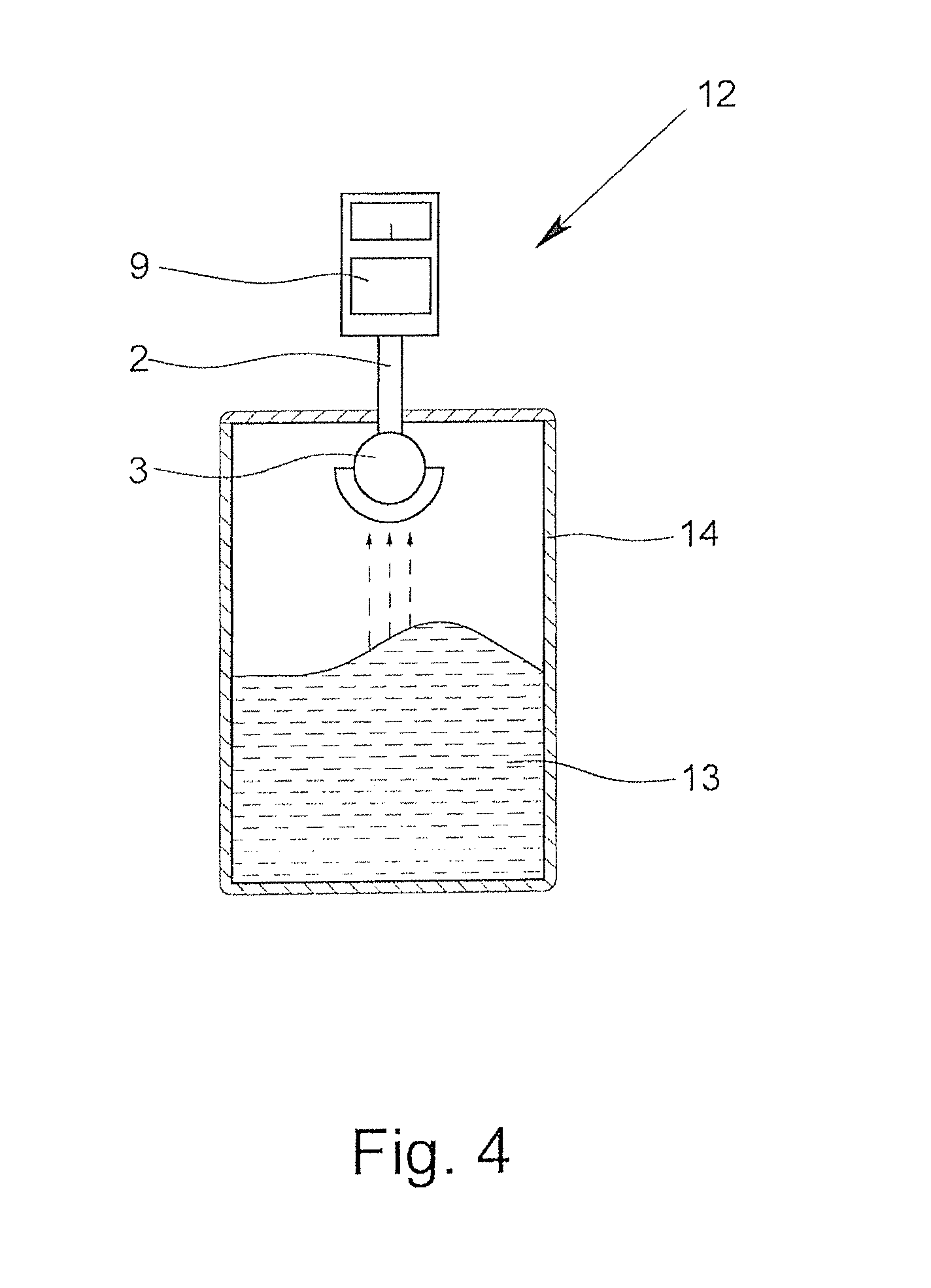
[0041]FIG. 1 shows a cross-sectional view through a schematically represented antenna 1 according to the invention having an indicated adjusting-directivity. A variation of the antenna 1 according to the invention is shown schematically in each of FIGS. 2 & 3. FIG. 4 schematically shows a construction (not to scale) for measuring the surface of a medium with a fill level sensor according to the invention.

[0042]The antenna 1 has supply element 2 that emits electromagnetic radiation—for example, in the form of spherical waves—to a dielectric lens 3. The lens 3 has an outer component 4 and an inner component 5. The outer component 4 has, in this example, the shape of a portion of a hollow sphere, here, a hemisphere. What is shown is how radiation in the form of a main beam, and here, two auxiliary beams, is formed at the position of the radiating surface 6 of the outer component 4, which is located opposite from the supply element 2.

[0043]In the illustrated example, the inner component...


PUM


Abstract

A dielectric antenna (1) having at least one supply element (2) and at least one lens (3) formed of a dielectric material. The dielectric antenna makes it possible to measure the surface of a medium with an essentially consistent measuring accuracy in that the lens (3) has an outer component (4) and an inner component (5). The outer component (4) has a radiating surface (6) that is spherical and an inner surface (7) that is spherical, and the inner component (5) has a contact surface (8) that spherical. Furthermore, the antenna is usable as part of a fill level sensor operating on the radar principle.

Description

BACKGROUND OF THE INVENTION[0001]1. Field of the Invention[0002]The invention relates to a dielectric antenna having at least one supply element and at least one lens consisting of at least one dielectric material, wherein the supply element emits electromagnetic radiation and supplies the lens with the electromagnetic radiation, wherein the lens guides the electromagnetic radiation further and radiates it.[0003]2. Description of Related Art[0004]In industrial measurement technology, radar fill level sensors are often used for determining the fill level of media, such as liquids, bulk materials and also slurries in containers, such as tanks or silos. The transit time method implemented by the measuring device is based on the physical law that the path, e.g., of an electromagnetic signal is equal to the product of transit time and propagation speed. In the case of measurement of the fill level of a medium—for example, a liquid or a bulk material—in a container, the path corresponds t...

Claims


Application Information

Patent Timeline
Patent Type & Authority Patents(United States)
IPC IPC(8): G01F23/284
CPCG01F23/284H01Q1/225H01Q13/02H01Q13/06H01Q15/08H01Q19/08H01Q3/14H01Q3/245
Inventor BAER, CHRISTOPHSCHULZ, CHRISTIANGERDING, MICHAEL
Owner KROHNE MESSTECHNICK GMBH & CO KG
Why Eureka
Try Eureka