Collapsible caged-ball prosthetic valve for transcatheter delivery and method of use

a transcatheter technology, applied in the field of collapsible caged ball prosthetic valve for transcatheter delivery and method of use, can solve the problems of increasing and achieve the effect of improving the durability of the valve and reducing the delivery profil

Inactive Publication Date: 2015-02-17
BOSTON SCI SCIMED INC
View PDF18 Cites 5 Cited by
  • Summary
  • Abstract
  • Description
  • Claims
  • Application Information

AI Technical Summary

Benefits of technology

[0008]The valves disclosed herein are embodiments of a new collapsible valve which can improve the valve durability and reduce the delivery profile. As discussed herein the valves are a stent based system with a ball or obstructer and are delivered by a delivery system through a blood vessel.

Problems solved by technology

However, one of the technical challenges of TAVI is to reduce the delivery profile and increase the durability of the valve.

Method used


Image

  • Collapsible caged-ball prosthetic valve for transcatheter delivery and method of use
  • Collapsible caged-ball prosthetic valve for transcatheter delivery and method of use
  • Collapsible caged-ball prosthetic valve for transcatheter delivery and method of use

Examples


Embodiment Construction

[0021]While this invention may be embodied in many different forms, there are described in detail herein specific embodiments of the invention. This description is an exemplification of the principles of the invention and is not intended to limit the invention to the particular embodiments illustrated.

[0022]For the purposes of this disclosure, like reference numerals in the figures shall refer to like features unless otherwise indicated.

A. The Valve and Methods of Making the Valve

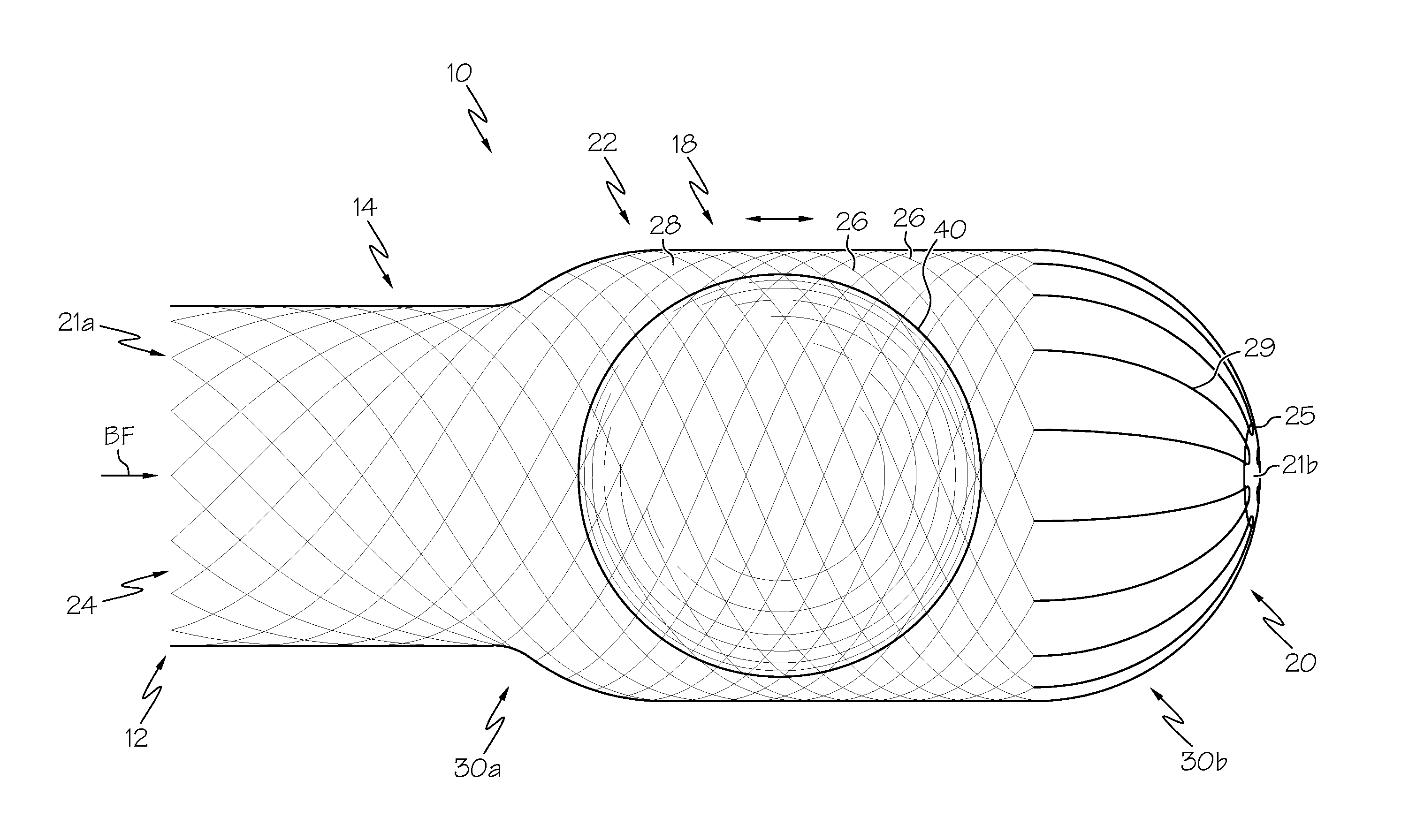
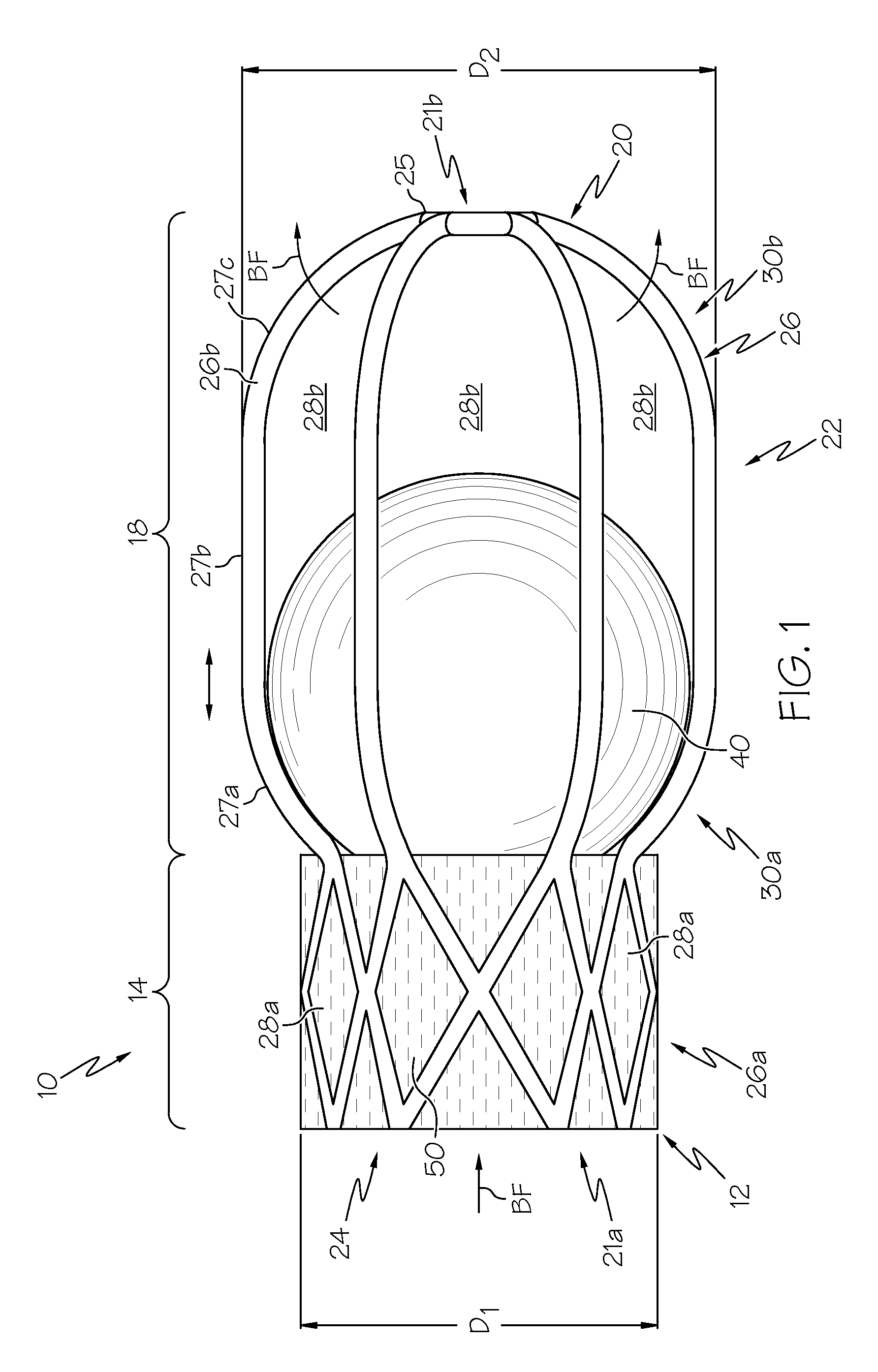
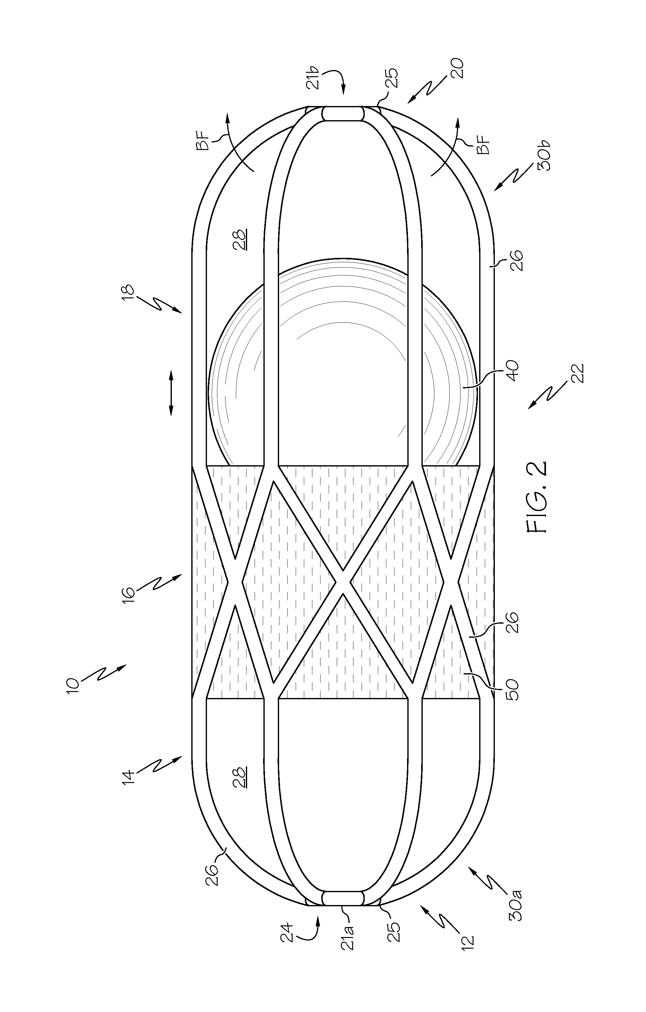
[0023]As shown in the figures, the valve 10 includes lumen 24, a proximal end 12, a distal end 20, a valve body 22, and an obstructer 40. As can be seen in FIGS. 1-8, the valve body 22 includes at least two regions 14, 16, 18, 30. As used in this application, the “proximal end”12 and the “distal end”20 of the valve 10 are determined relative to the flow of blood (BF) through the valve 10, with blood flow entering the valve 10 at the proximal end 12 and the distal end 20 being the other end of the valve 10. ...


PUM


Abstract

A valve that includes an expandable valve body defining a lumen and a longitudinally moveable obstructer retained within the lumen of the valve body between the proximal and distal ends of the valve when the valve is in an expanded configuration. The valve, in the collapsed configuration, is delivered to a native valve site by a catheter where the valve body is expanded to anchor the valve at the valve annulus and the collapsed obstructer is subsequently expanded so that the valve is in the expanded configuration.

Description

CROSS-REFERENCE TO RELATED APPLICATIONS[0001]This application claims priority to U.S. Patent Provisional Application No. 61 / 671,210, filed Jul. 13, 2012, the entire contents of which are hereby incorporated herein by reference.STATEMENT REGARDING FEDERALLY SPONSORED RESEARCH[0002]Not ApplicableBACKGROUND OF THE INVENTION[0003]Valve replacement may be indicated when there is a narrowing of the native valve, commonly referred to as stenosis, or when the native valve leaks or regurgitates. Examples of valves that may be replaced include heart valves and venous valves. Valve replacement is used to repair or replace a diseased valve. To replace a heart valve, one method is open heart surgery. Another method to replace a heart valve, typically an aortic valve, is transcatheter aortic valve implantation (TAVI), developed to treat high-risk or inoperable severe aortic stenosis patients, which is known to have a poor prognosis clinically. Currently, TAVI is a fast growing procedure, with mor...

Claims


Application Information

Patent Timeline
Patent Type & Authority Patents(United States)
IPC IPC(8): A61F2/24A61F2/06
CPCA61F2/06A61F2/2409A61F2/2424A61F2/2436A61F2250/0003
Inventor WANG, HUISUNZHOU, PU
Owner BOSTON SCI SCIMED INC
Why Eureka
Try Eureka