Check patentability & draft patents in minutes with Patsnap Eureka AI!

System and method for manufacturing a lens, such as an ophthalmic lens

a manufacturing system and lens technology, applied in the field of ophthalmic lenses, can solve the problems of sharp edges, edge breakage, and thin edges that are often broken during manufacturing, and the creation of lens surfaces is often limited to generally spherical surfaces

Active Publication Date: 2015-05-26
DIGITAL VISION
View PDF44 Cites 5 Cited by
  • Summary
  • Abstract
  • Description
  • Claims
  • Application Information

AI Technical Summary

Benefits of technology

Enables the production of high plus power and prismatic lenses without sharp edges, reducing equipment damage and manufacturing costs, while maintaining lens thickness and preventing coating errors, thus improving manufacturing efficiency and user comfort.

Problems solved by technology

Using lathes and laps, the creation of surfaces on lens has often been limited to generally spherical surfaces because the lap can only apply curves to the back surfaces on lenses that maintain the same radius of curvature through the surface.
There are various problems associated with creating sharp points on lens blanks during manufacturing, namely:The sharp, thin edge often breaks during manufacturing.
The pads often get caught in the sharp edge during polishing and the edge breaks off.The sharp, thin edge often ruins equipment used during manufacturing.
This can greatly affect the speed of manufacturing, not to mention the costs associated with manufacturing a lens.
Additionally, should a thin edge break off, any subsequent processes may be affected.
For example, an edger having a cutting blade tends to slip when a lens to be edged (that is, the periphery is to be removed) is jagged or has pieces broken off.The sharp, thin edge does not allow for automated manufacturing.
Because the sharp edges are thin and require care when handling, inspectors and other manufacturing personnel are required to regulate the stages of the manufacturing process.The sharp, thin edge can lead to improper coating of a lens.
For example, when a coating (e.g., an anti-reflective coating) is being applied to a front surface of a lens blank having a thin edge, the application of the coating will often wrap around the thin edge and be applied to the back surface, which is undesirable and can ruin a lens.
Typically, manufacturers add unwanted and / or unneeded thickness to the entire lens to offset the thinning or sharpening at the periphery where a front curve and a back curve meet.
However, adding thickness leads to lenses that are bulky and inconvenient to a user wearing eyeglasses with such lenses.
Also, the additional thickness in the center portion increases the magnification, appearance, and weight of the lens, causing the wearer of the lens (i.e., in eyeglasses) cosmetic and physical discomfort.

Method used


Image

  • System and method for manufacturing a lens, such as an ophthalmic lens
  • System and method for manufacturing a lens, such as an ophthalmic lens
  • System and method for manufacturing a lens, such as an ophthalmic lens

Examples


Embodiment Construction

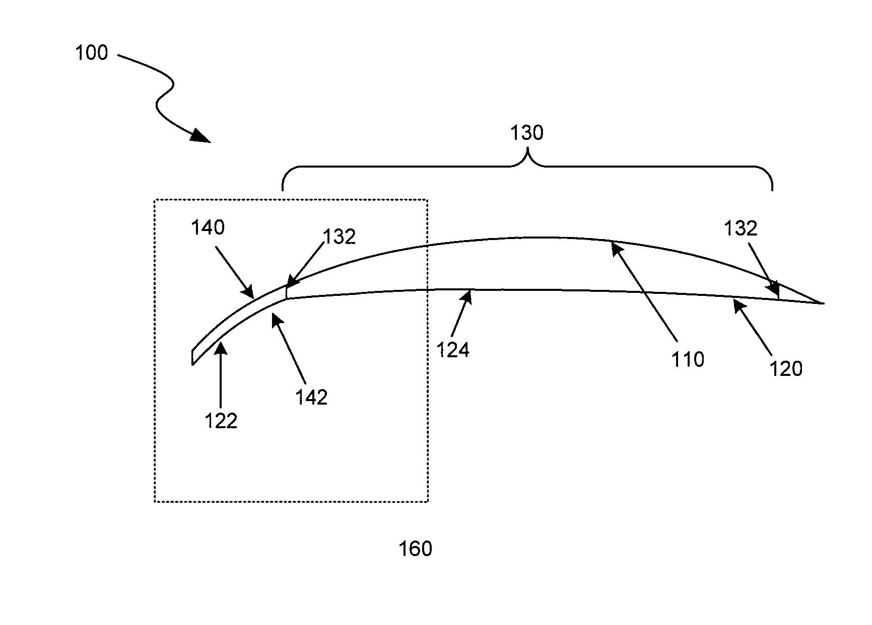
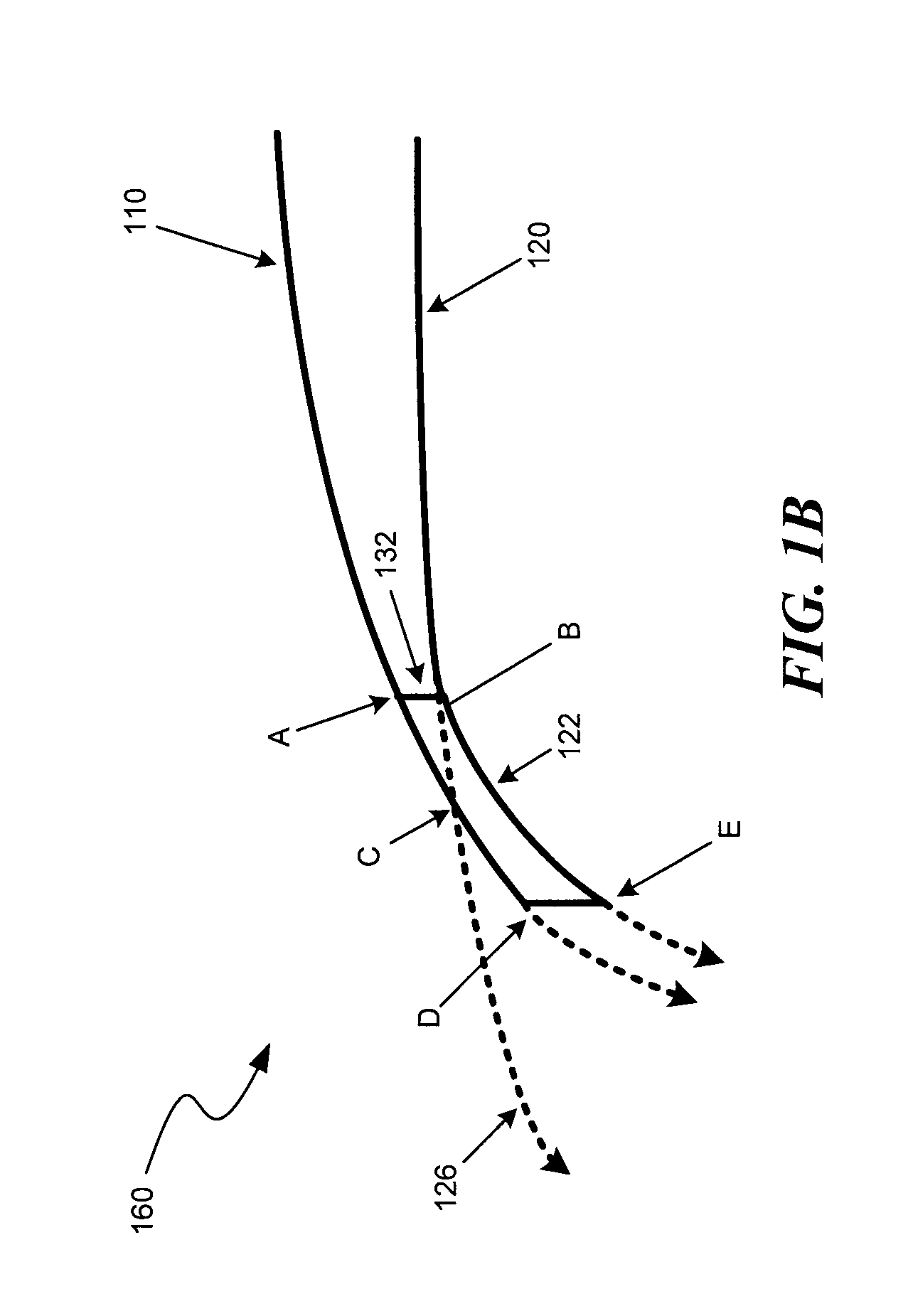
A system and method for modifying a periphery of a lens blank during manufacturing of the lens is described. In some examples, the system creates a back surface on a lens blank having a specified radius of curvature at the part of the lens blank containing a prescription, and a different radius of curvature at the periphery of the lens blank. The system may produce curves on lens surfaces that non-spherically change in curvature from the center of the lens to the periphery. For example, the system may create conic-based surfaces, such as hyperbolic surfaces, that are substantially spherical, cylindrical, or spherocylindrical throughout the prescription portion of the lens and substantially aspherical past the prescription portion of the lens (that is, the portion to be ultimately removed when fitting the lens to an eyeglass frame).

In some cases, the system may employ digital surfacing in creating the curves on the lens surfaces. Digital surfacing, and other soft tool based surfacing...


PUM

PropertyMeasurementUnit
thicknessaaaaaaaaaa
thicknessaaaaaaaaaa
radius of curvatureaaaaaaaaaa

Abstract

A system and method for manufacturing an ophthalmic lens is described. In some examples, the system applies a back surface to a lens blank that includes an aspherical curve having two radii of curvature. In some examples, a back surface of a peripheral portion of the lens follows the curvature of a front surface of the lens in order to establish a rounded, non-sharp edge to a lens blank used during the manufacturing process of a prescription eyeglass lens.

Description

BACKGROUNDTraditionally, the manufacturing of a lens for use in eyeglasses requires a number of steps, including: (1) choosing a semi-finished lens blank with a finished front surface (base curve) and an unfinished back surface, (2) grinding the back surface with a lathe, such as a toric lathe, that creates a spherical concave or convex surface (such as a cylindrical or spherical surface) on the back surface to place an optical system on the surface used to correct the vision of a user of eyeglasses, and (3) lapping the back surface to smooth the surface to a desired curvature to finish the optical system. Further steps may include polishing and smoothing the lens. Using lathes and laps, the creation of surfaces on lens has often been limited to generally spherical surfaces because the lap can only apply curves to the back surfaces on lenses that maintain the same radius of curvature through the surface.When creating high power lenses, such as high plus power and / or high prismatic l...

Claims


Application Information

Patent Timeline
Patent Type & Authority Patents(United States)
IPC IPC(8): G02C7/02B24B1/00B24B13/00
CPCB24B13/00B24B1/00
Inventor ARRIGOTTI, STANKEANE, GORDON
Owner DIGITAL VISION
Features
  • R&D
  • Intellectual Property
  • Life Sciences
  • Materials
  • Tech Scout
  • Unparalleled Data Quality
  • Higher Quality Content
  • 60% Fewer Hallucinations
Learn More