Operation input device

a technology of operation input and input surface, which is applied in the direction of instruments, computing, electric digital data processing, etc., can solve the problems of difficult to accurately perform the operation of the operation surface of the touch pad, the difficulty of discriminating through tactile sensation between the standing fiber hair and the non-standing fiber hair, and the inability to accurately perform the operation

Inactive Publication Date: 2015-06-23
AISIN AW CO LTD
View PDF15 Cites 14 Cited by
  • Summary
  • Abstract
  • Description
  • Claims
  • Application Information

AI Technical Summary

Benefits of technology

[0010]According to the above configuration, a predetermined operation can be input to another device communicably connected to the operation input device in accordance with the position of the object to be sensed in contact with or in proximity to the operation surface of the touch pad. The hole portion is provided in the operation plate on the surface of the touch pad, and the protrusion member is inserted into the hole portion. The protrusion member is driven by the drive mechanism so as to be advanced and retracted along a direction intersecting the operation surface between the first state and the second state. Therefore, when the protrusion member is in the first state, the distal end portion of the protrusion member is distinctly protruded from the operation surface to provide a user with an operation feeling that utilizes tactile sensation. When the protrusion member is in the second state, the distal end portion of the protrusion member is retracted to the back surface side with respect to the operation plate (or flush with the operation surface), which makes the operation surface of the touch pad flat. Thus, an operation performed on the touch pad by the user is not impeded. That is, by controlling the protrusion member so as to be advanced and retracted between the first state and the second state, it is possible to provide the user with an operation feeling that utilizes tactile sensation without impairing the operation feeling of the touch pad experienced by the user. By bringing the protrusion member positioned at the coordinates on the operation surface corresponding to the coordinates of an operation figure displayed on a display device into the first state, for example, the user may perform operation input to the operation surface at that position in reliance on the protrusion member in the first state. Thus, it is possible to provide an operation input device that enables to perform reliable operation input compared to the related art without closely watching a display screen. Further, by bringing the protrusion member into the second state in the case where an operation figure is not displayed on the display device, for example, the user may smoothly perform operation input to the operation surface without being hindered by the protrusion member.
[0012]According to the above configuration, the distal end portion of the protrusion member can be configured to appear and disappear from the operation surface without impairing the function of the touch pad of the capacitance type even in the case where the conductive wiring members are disposed in a grid along the operation surface of the touch pad in order to sense the object to be sensed.
[0014]According to the above configuration, the protrusion member can be moved by the drive mechanism between the first state and the second state utilizing the characteristics of the piezoelectric element which converts an electric signal into a physical force and vice versa. In addition, providing a configuration that enables to sense an external force applied to the piezoelectric element via the protrusion member as an electric signal may achieve a configuration that enables to sense an operation for the protrusion member performed by the user.
[0016]According to the configuration, the piezoelectric element can be vibrated along the advancing / retracting operation direction of the protrusion member to drive the protrusion member along the advancing / retracting operation direction. In this event, the protrusion member can be moved to the protrusion direction side by the vibration control section making the speed of vibration of the piezoelectric element to the protrusion direction side (surface side with respect to the operation surface) lower than the speed of vibration of the piezoelectric element to the side opposite to the protrusion direction side (back surface side with respect to the operation surface), by utilizing a difference between static friction and dynamic friction caused between the piezoelectric element or a member that vibrates together with the piezoelectric element and the protrusion member. Conversely, the protrusion member can be moved to the side opposite to the protrusion direction side by the vibration control section making the speed of vibration of the piezoelectric element to the protrusion direction side higher than the speed of vibration of the piezoelectric element to the side opposite to the protrusion direction side. Hence, the drive mechanism which moves the protrusion member between the first state and the second state can be formed appropriately.

Problems solved by technology

When driving, it is difficult to perform these operations while closely watching the display screen, and thus, a desired operation may not be performed accurately.
Thus, it is difficult to discriminate through tactile sensation between the standing fiber hair and the non-standing fiber hair.
Further, the entirety of the operation surface is covered with fiber hair at all times. Thus, an operation performed on the operation surface (such as a slide operation, for example) is not impeded, which makes it difficult to perform operation input to the operation surface of the touch pad accurately.

Method used


Image

  • Operation input device
  • Operation input device
  • Operation input device

Examples


Embodiment Construction

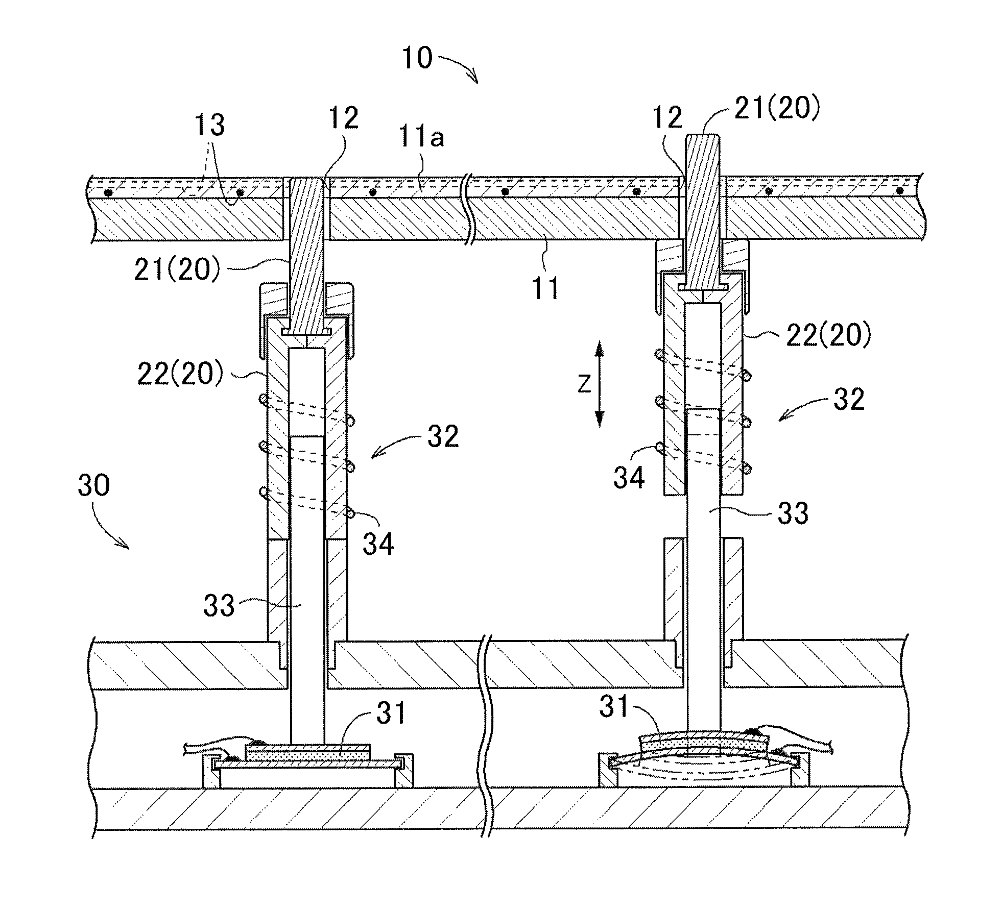
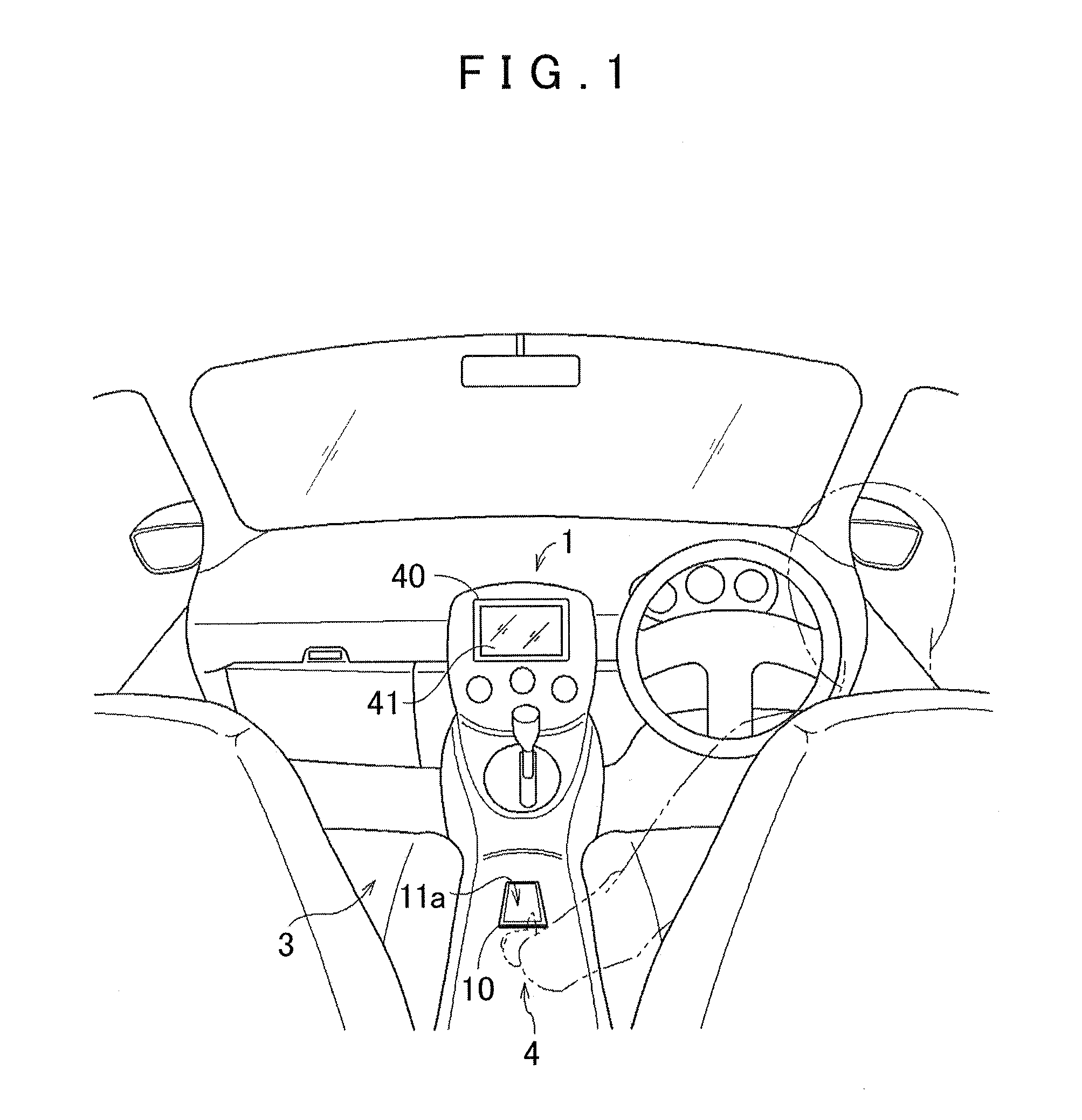
[0034]An operation input device according to an embodiment of the present invention will be described with reference to the drawings. In the embodiment, an operation input device 4 configured to perform an (predetermined) operation input prescribed in advance to an in-vehicle navigation apparatus 1 (see FIG. 1) is described. The operation input device 4 forms an operation input system 3 together with a display input device 40 communicably connected to the navigation apparatus 1. In the following, a schematic configuration of the navigation apparatus 1, the configuration of the operation input device 4, the configuration of the operation input system 3, and the procedures of an operation input reception process are described below.

1. Schematic Configuration of Navigation Apparatus

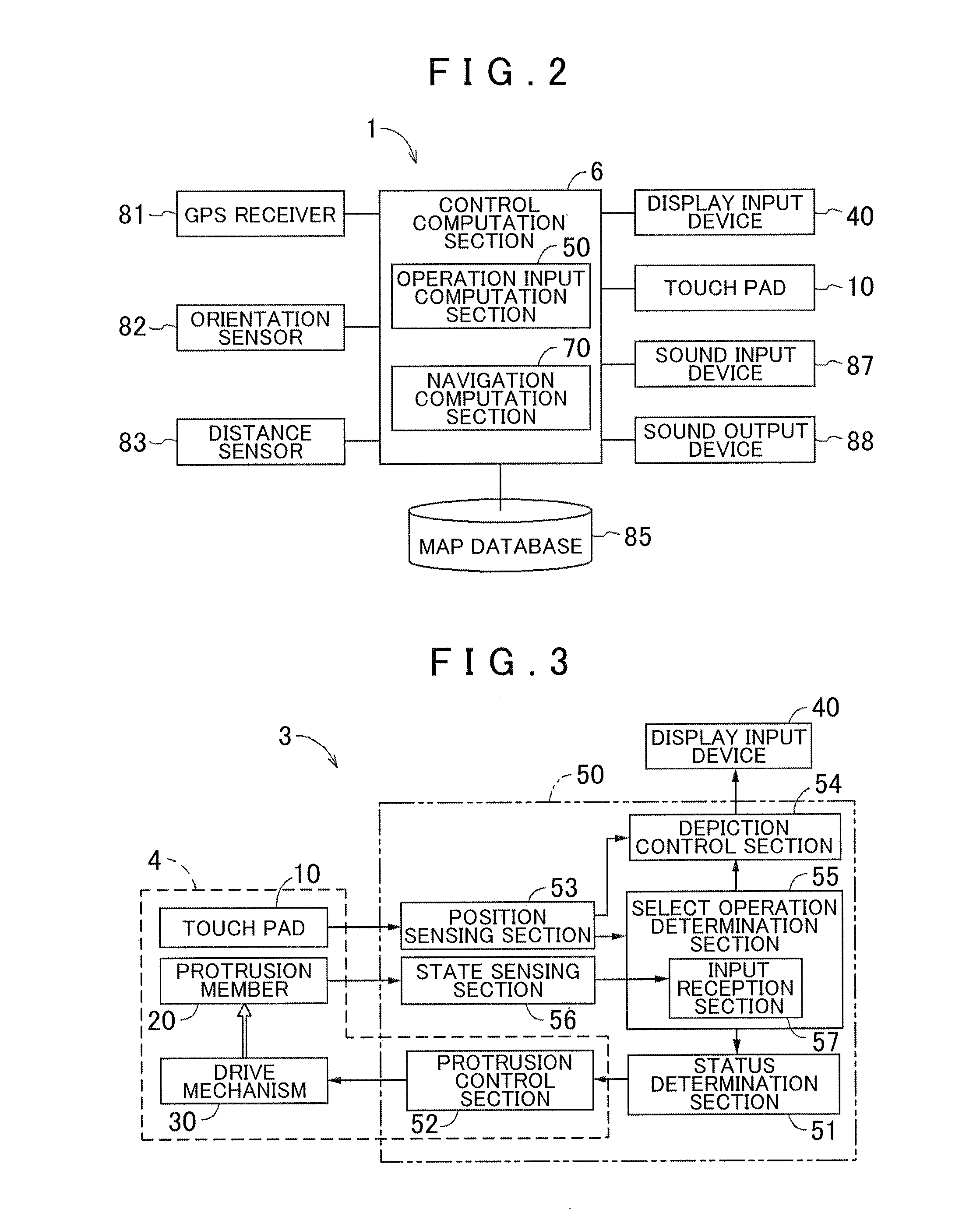
[0035]A schematic configuration of the navigation apparatus 1 is described with reference to FIGS. 1 and 2. The navigation apparatus 1 is configured to achieve basic functions such as displaying the vehicle ...


PUM


Abstract

An operation input device system and method are provided. The operation input device includes a touch pad having an operation plate on a surface of which an operation surface is formed. The touch pad is configured to sense an object in contact with or in proximity to the operation surface to receive input corresponding to a position of the sensed object. A hole portion provided to penetrate through the operation plate and a protrusion member inserted into the hole portion. The operation input device also includes a drive mechanism provided on a back surface side of the operation plate and configured to cause an advancing / retracting operation of the protrusion member along a direction intersecting the operation surface between a first state in which a distal end portion of the protrusion member is above the operation surface and a second state in which the distal end portion is not above the operation surface.

Description

INCORPORATION BY REFERENCE[0001]This application claims priority from Japanese Patent Application No. 2011-286486 filed on Dec. 27, 2011, including the specification, drawings and abstract thereof, the disclosure of which is incorporated herein by reference in its entirety.BACKGROUND OF THE INVENTION[0002]1. Field of the Invention[0003]Aspects of the present invention relate to an operation input device including a touch pad serving as a pointing device.[0004]2. Description of the Related Art[0005]Devices including an operation input device as standard equipment, are commonly utilized in laptop personal computers etc., for example. The operation input devices may include a touch pad serving as a pointing device. In these types of devices, a user performs various slide operations using their fingertips, the tip of a stylus pen, or the like, on an operation surface provided on an outer surface of the touch pad to move an operation cursor displayed on a display screen, which is communi...

Claims


Application Information

Patent Timeline
Patent Type & Authority Patents(United States)
IPC IPC(8): H01L41/08H01H57/00G06F3/044G06F3/0354
CPCH01H57/00G06F3/044G06F3/03547G06F3/016G06F3/0443G06F3/0446
Inventor TAKA, YOICHIROKOYAMA, RYOJIADACHI, KAZUHIDE
Owner AISIN AW CO LTD
Why Eureka
Try Eureka