

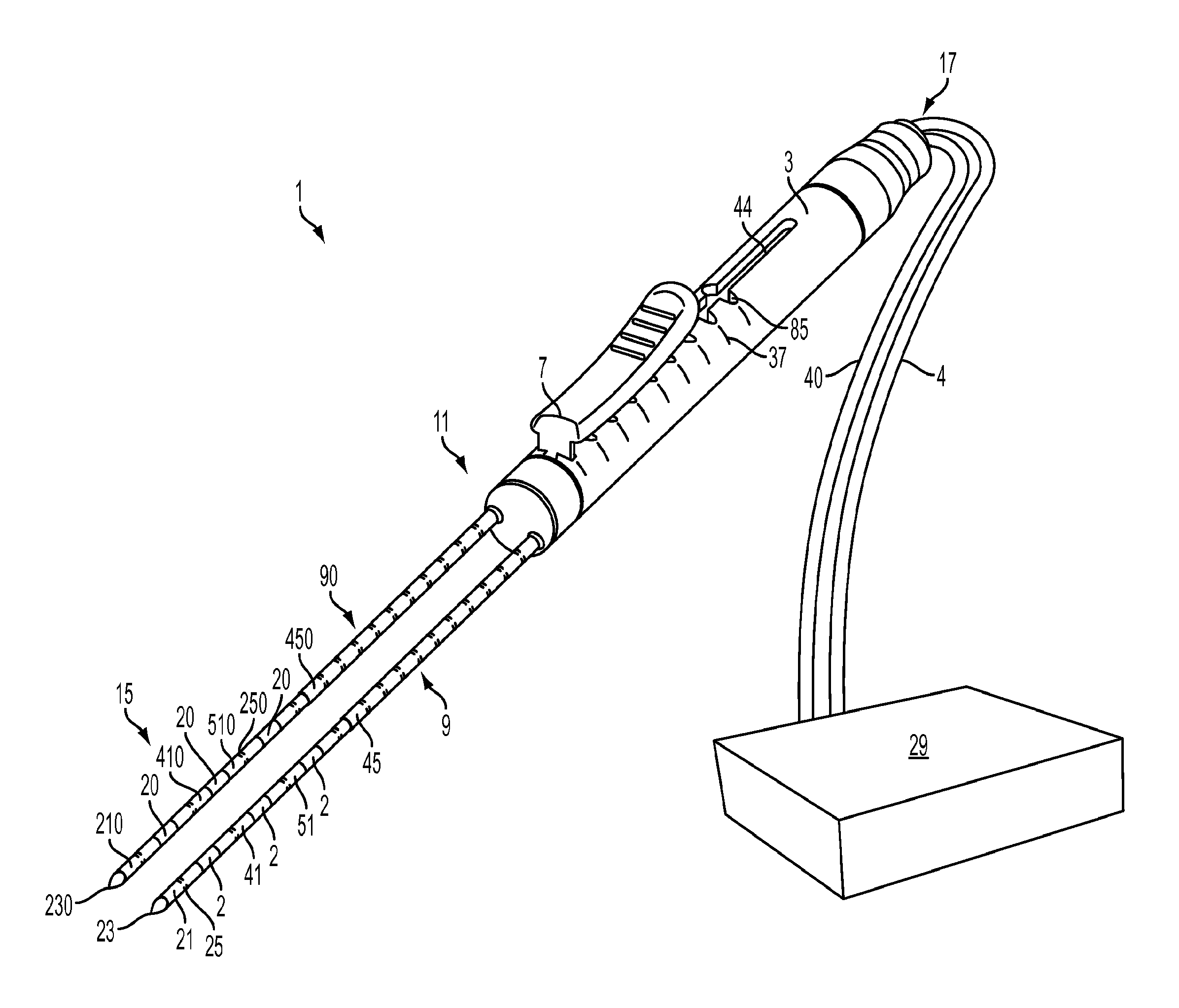
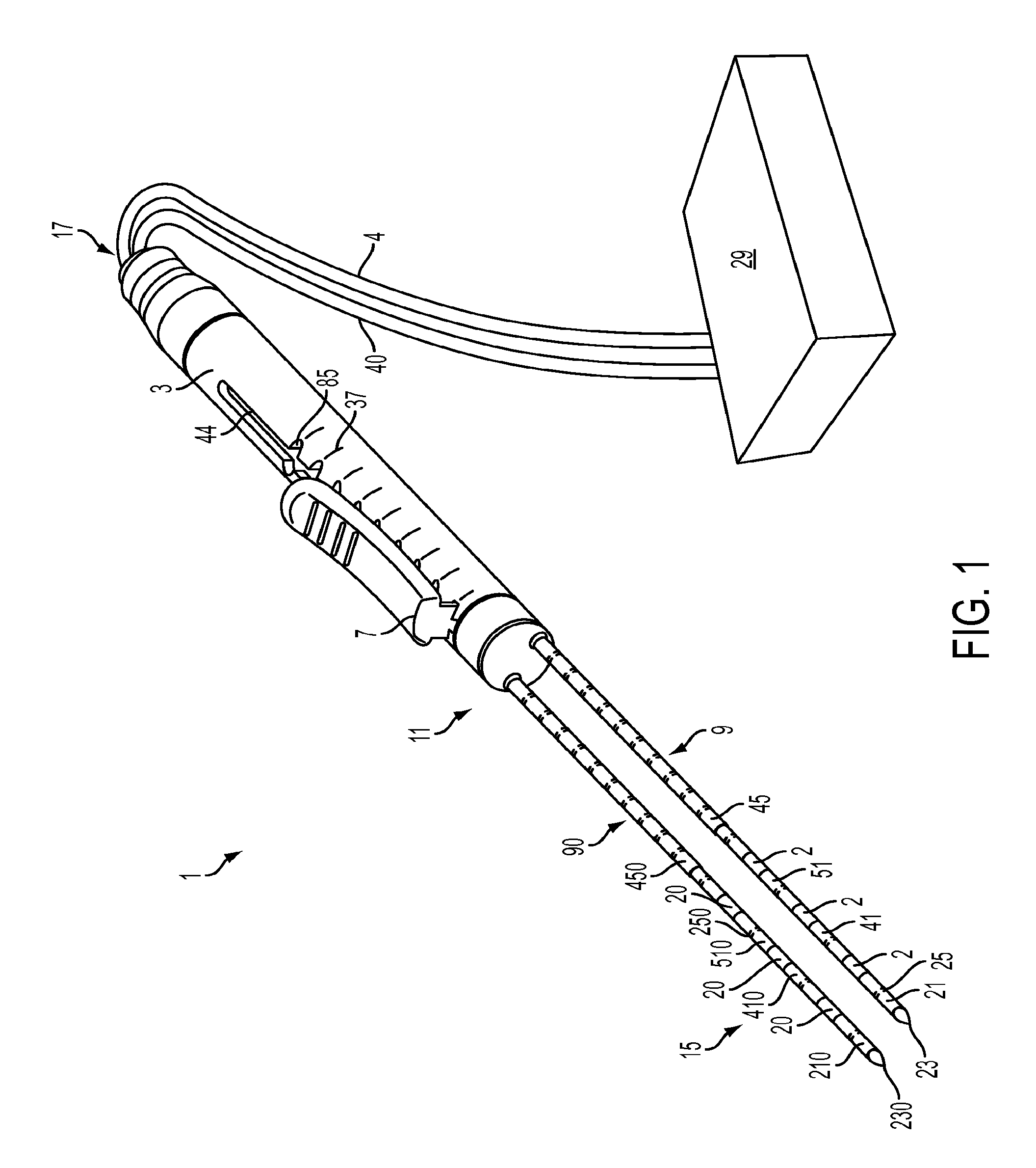
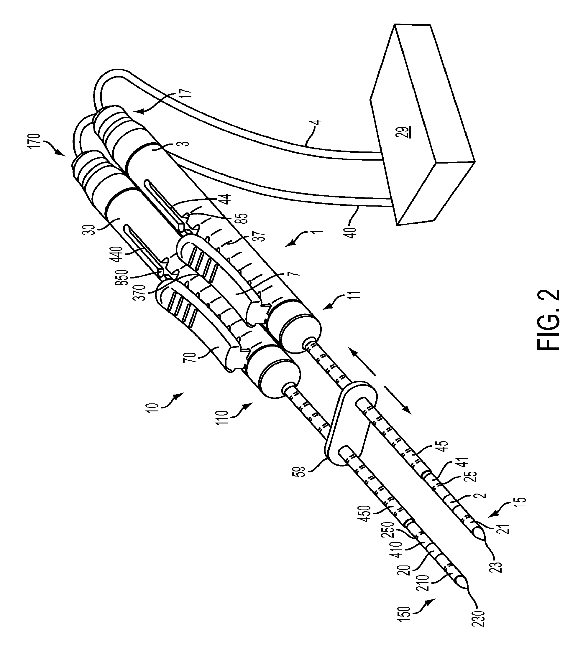
Multiple treatment zone ablation probe
a multi-treatment zone and ablation probe technology, applied in the field of multi-treatment zone ablation probes, can solve the problems of increasing the chances of missing portions of the target tumor tissue, killing and destroying the target tissue, and difficult for physicians to keep all of the probes parallel for ablation,
- Summary
- Abstract
- Description
- Claims
- Application Information
AI Technical Summary
Benefits of technology
Problems solved by technology
Method used
Image

Examples
Embodiment Construction
[0042]The present invention can be understood more readily by reference to the following detailed description and the examples included therein and to the Figures and their previous and following description. The drawings, which are not necessarily to scale, depict selected embodiments and are not intended to limit the scope of the invention. The detailed description illustrates by way of example, not by way of limitation, the principles of the invention.
[0043]The skilled artisan will readily appreciate that the devices and methods described herein are merely exemplary and that variations can be made without departing from the spirit and scope of the invention. It is also to be understood that the terminology used herein is for the purpose of describing particular embodiments only and is not intended to be limiting.
[0044]Ranges can be expressed herein as from “about” to one particular value, and / or to “about” another particular value. When such a range is expressed, another embodime...
PUM
 Abstract
Description
Claims
Application Information