Check patentability & draft patents in minutes with Patsnap Eureka AI!

Method and device for producing a pipe member

a technology of pipe member and pipe body, which is applied in the field of method and device for producing pipe member, can solve the problems of inability to meet the requirements for weight reduction and material cost reduction, the thickness of the pipe member is difficult to reduce, and the outer diameter of the pipe is limited, so as to reduce the required amount of thermoplastic material and thin the resultant product.

Active Publication Date: 2016-04-26
SANOH IND CO LTD
View PDF8 Cites 1 Cited by
  • Summary
  • Abstract
  • Description
  • Claims
  • Application Information

AI Technical Summary

Benefits of technology

[0018]The present invention was contrived in view of the background art described above, and an object thereof is to provide a method and device for producing a pipe member, which is capable of making the thickness of a resultant product as thin as possible and reducing the required amount of thermoplastic material, without complicating the device.

Problems solved by technology

It is difficult to reduce the thickness of the pipe member.
For this reason, the requirement specifications and the requests for weight reduction and material cost reduction cannot be met.
For example, when replacing a metallic pipe of an automobile with a resin pipe obtained through fluid-assisted injection molding, there is a limit in increasing the outer diameter of the pipe from the viewpoint of the layout of the pipe.
Therefore, a problem in a cooling pipe, for example, is that an expensive large pump with high energy consumption is required.
This generates a large amount of excess thermoplastic material to be pushed out, resulting in an increase in the cost of recycling the thermoplastic material.
Another problem is that this method requires a large injection molding machine that has an injection unit with an injection volume larger than the volume of a hollow molded article.
This method, therefore, is considered uneconomical.
However, this method, too, is not a technology for making the pipe part as thin as possible, the pipe part being formed at least by the pressurized fluid.
However, such configuration in which the different types of molding materials are introduced into the molding die complicates at least an device for forming the hollow part, thus creating a new problem of an equipment cost increase.

Method used


Image

  • Method and device for producing a pipe member
  • Method and device for producing a pipe member
  • Method and device for producing a pipe member

Examples


Embodiment Construction

[0045]Embodiments of the method and device for producing a pipe member according to the present invention are described hereinafter in detail with reference to the drawings.

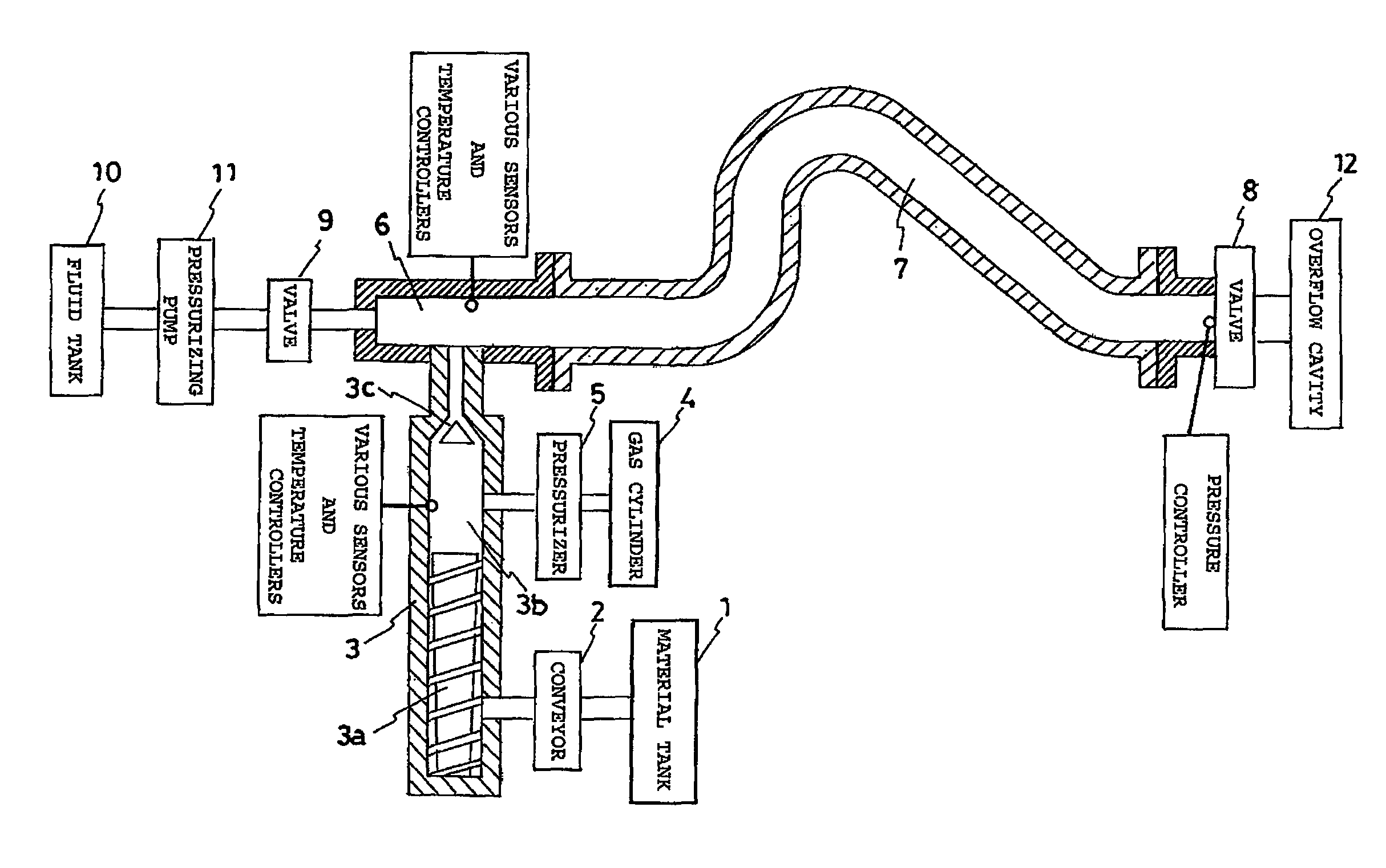
[0046]FIG. 1 is a schematic diagram showing an example of an embodiment of the method and the device according to the present invention.

[0047]In the embodiment shown in the diagram, a thermoplastic material is stored in a material tank 1.

[0048]Various materials such as thermoplastic and thermoplastic elastomer, for example, can be used as the thermoplastic material. Examples of the thermoplastic include polyolefin resins such as polyethylene and polypropylene resin, polyester resin, polyamide resin, polyphthal-amide resin, polyphenylene sulphide resin, and polycarbonate resin. Examples of the thermoplastic elastomer include polyolefin thermoplastic elastomer, chlorinated polyethylene thermoplastic elastomer, polystyrene thermoplastic elastomer, polyurethane thermoplastic elastomer, polyester thermoplastic elastom...


PUM

PropertyMeasurementUnit
pressureaaaaaaaaaa
temperatureaaaaaaaaaa
pressureaaaaaaaaaa

Abstract

An object of the present invention is to provide a method for producing a pipe, which is capable of reducing the amount of thermoplastic material, without complicating an device for producing a pipe. The present invention provides a method for producing a pipe, comprising a thermoplastic material filling process for filling a die with a thermoplastic material, and a thermoplastic material discharging process for pushing out an unsolidified part of the thermoplastic material in the molding die using pressurized fluid, wherein the thermoplastic material is mixed with a foaming agent, the method further comprises a process for foaming the thermoplastic material filling the molding die, and the thermoplastic material discharging process is a process for pushing out a inner part of the thermoplastic material foamed in the molding die, by using the pressurized fluid prior to solidification of the inner part.

Description

TECHNICAL FIELD[0001]The present invention relates to a method and device for producing a pipe member, which perform so-called fluid-assisted injection molding having a thermoplastic material filling process for filling a molding die with a thermoplastic material and a thermoplastic material discharging process for extruding an unsolidified part of the thermoplastic material in the molding die by using pressurized fluid.BACKGROUND ART[0002]Fluid-assisted injection molding is known as a method for producing a pipe member.[0003]FIGS. 4 and 5 each schematically show a method for producing a pipe member according to a conventional technology in which the fluid-assisted injection molding is used.[0004]FIG. 4 is a diagram showing a state of a thermoplastic material in a molding die cavity in a thermoplastic material filling process according to the conventional technology, wherein FIG. 4(a) is a longitudinal cross-sectional diagram taken along an axial direction of the thermoplastic mater...

Claims


Application Information

Patent Timeline
Patent Type & Authority Patents(United States)
IPC IPC(8): B29C45/26B29C43/02B29C45/17B29C44/42B29K105/12B29L23/00
CPCB29C43/02B29C44/42B29C45/1711B29C2045/1719B29C2045/1728B29K2105/12B29L2023/004
Inventor EZURE, KAZUHIROMOTONAGA, MASAOMIEDA, NAOYA
Owner SANOH IND CO LTD
Features
  • R&D
  • Intellectual Property
  • Life Sciences
  • Materials
  • Tech Scout
  • Unparalleled Data Quality
  • Higher Quality Content
  • 60% Fewer Hallucinations
Learn More