Electromechanically actuable motor vehicle brake with selective self-locking

a motor vehicle and self-locking technology, applied in mechanical devices, braking systems, transportation and packaging, etc., can solve the problems of self-locking preventing the use of electro-mechanical actuation functions for application, and the motor vehicle brake can only be used as a parking brake, etc., and achieve the effect of simple construction

Active Publication Date: 2016-05-17
LUCAS AUTOMOTIVE GMBH
View PDF21 Cites 7 Cited by
  • Summary
  • Abstract
  • Description
  • Claims
  • Application Information

AI Technical Summary

Benefits of technology

[0007]A feature of the present invention is to provide an electromechanically actuable motor vehicle brake which can be used both as a service brake and as a parking brake, and which in a simple construction reliably prevents unintentional release or reduction of the parking brake action.
[0009]The invention has the advantage that using a wrap spring clutch which is arranged in the flow of force between the motorised drive and the spindle can ensure on the one hand that the torque applied by the motorised drive can be reliably transmitted to the spindle for applying or actuating the motor vehicle brake; on the other hand, the wrap spring clutch is constructed such that the reaction forces acting from the brake pad back through the spindle, which would cause the brake action to be released, for example in a parking brake situation, are reliably blocked by the wrap spring clutch. In this way, the wrap spring clutch forms a self-switching overrunning clutch which enables torque to be transmitted towards the spindle over a long period but can block the transmission of torque in the opposite direction, from the spindle to the motorised drive. This makes it possible to avoid the self-locking in the gear provided, for example, in the prior art. As a result, the electromechanical motor vehicle brake is also suitable for use as a service brake. Furthermore, this makes it possible to save on additional switching elements such as the lever mechanism from the prior art, described at the outset. In this connection, an additional trigger control for these switching elements is also dispensed with.
[0010]A further development of the invention provides for the gear arrangement to have at least two gear wheels which may be connected to one another such that torque is transmitted by way of the wrap spring clutch, by means of a wrap spring. This makes it possible to integrate the wrap spring clutch in the gear arrangement in space-saving manner and to accommodate it such that it is protected between the two gear wheels.

Problems solved by technology

However, the self-locking has the disadvantage that within the scope of its electromechanical actuation this motor vehicle brake can only be used as a parking brake.
The self-locking hinders use of the electro-mechanical actuation function for application during service braking, since it would block release of the brake.

Method used


Image

  • Electromechanically actuable motor vehicle brake with selective self-locking
  • Electromechanically actuable motor vehicle brake with selective self-locking
  • Electromechanically actuable motor vehicle brake with selective self-locking

Examples


Embodiment Construction

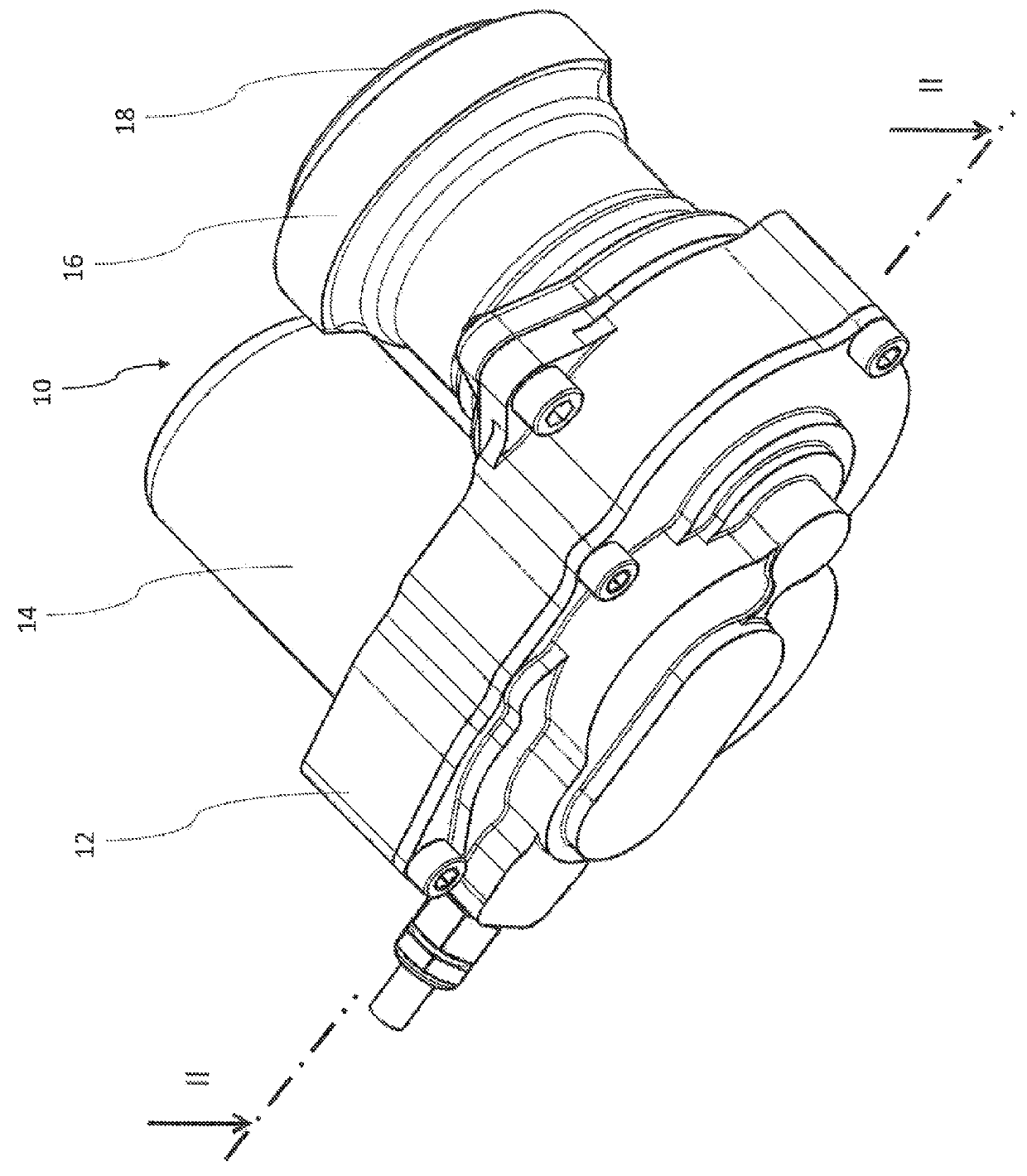
[0026]FIG. 1 shows an actuator subassembly of a motor vehicle brake according to the invention in a perspective illustration, overall designated 10. In particular, FIG. 1 shows a housing 12, in which there is arranged a gear arrangement, a part housing 14 for accommodating a drive motor and a further part housing 16 in which there is arranged a displaceable piston 18 by means of which a brake pad (not shown) can be displaced in a brake unit of a motor vehicle brake in a manner activating braking. The actuator subassembly 10, shown in FIG. 1, of the motor vehicle brake according to the invention can be installed for example in a floating-calliper brake in conventional manner. In this respect, reference is made to WO 2009 / 046899 A1, where an installation situation of this kind is shown by way of example. This document is an application of the present Applicant. Because the topic of the text below is the actuator subassembly comprising motorised drive and movement mechanism for moving ...


PUM


Abstract

A motor vehicle brake, in particular an electromechanically actuable motor vehicle brake, having an actuator subassembly, including a housing, a servo element which is movable in relation to the housing, for moving a brake pad, a motorized drive, a movement mechanism arranged between the motorized drive and the movable servo element, a gear arrangement associated with the movement mechanism, wherein the movement mechanism has a ball screw with a spindle that can be driven in rotation and a nut that can be displaced linearly in the housing, wherein the nut may be moved, for moving the servo element, by driving the spindle in rotation within the housing. In this motor vehicle brake it is provided for the gear arrangement to have a wrap spring clutch which is arranged in the flow of force between the motorized drive and the spindle such that the wrap spring clutch permits torque to be transmitted from the motorized drive to the spindle, and is constructed to block transmission of torque from the spindle to the motorized drive.

Description

CROSS-REFERENCE TO RELATED APPLICATIONS[0001]This application is a national stage of International Application No. PCT / EP2012 / 001570 filed Apr. 11, 2012, the disclosures of which are incorporated herein by reference in entirety, and which claimed priority to German Patent Application No. DE 10 2011 102 860.2 filed May 31, 2011, the disclosures of which are incorporated herein by reference in entirety.BACKGROUND OF THE INVENTION[0002]The invention relates to an electromechanically actuable motor vehicle brake having an actuator subassembly, including a housing, a servo element which is movable in relation to the housing, for moving a brake pad, a motorised drive, a movement mechanism arranged between the motorised drive and the movable servo element, and a gear arrangement associated with the movement mechanism, wherein the movement mechanism has a ball screw with a spindle that can be driven in rotation and a nut that can be displaced linearly in the housing, wherein the nut may be ...

Claims


Application Information

Patent Timeline
Patent Type & Authority Patents(United States)
IPC IPC(8): B60L7/00B60T13/74F16D65/18F16D121/24F16D125/40F16D125/50F16D127/06
CPCB60T13/741F16D65/18B60T13/746F16D2121/24F16D2125/40F16D2125/50F16D2127/06B60T13/74
Inventor GIERING, WILFRIED
Owner LUCAS AUTOMOTIVE GMBH
Why Eureka
Try Eureka