Check patentability & draft patents in minutes with Patsnap Eureka AI!

Harmonic drive assembly with selective disconnect and method

a drive assembly and selective disconnect technology, applied in the direction of power amplification, mechanical equipment, gearing, etc., can solve the problems of difficult backup system to overcome the primary system and control the flight control surfa

Active Publication Date: 2016-05-31
HAMILTON SUNDSTRAND CORP
View PDF7 Cites 1 Cited by
  • Summary
  • Abstract
  • Description
  • Claims
  • Application Information

AI Technical Summary

Benefits of technology

[0004]According to another embodiment, a method of disconnecting a harmonic drive assembly is provided. The method includes retracting a wave generator of a harmonic drive and a motor drive shaft out of a flex gear of the harmonic drive. The method also includes disengaging a plurality of flex gear teeth of the flex gear from a plurality of ring gear teeth of a ring gear of the harmonic drive, wherein disengaging the flex gear teeth and the ring gear teeth provides a clearance therebetween.

Problems solved by technology

The primary system may have become stuck or jammed in one position, making it difficult for the backup system to overcome the primary system and control the flight control surface.

Method used


Image

  • Harmonic drive assembly with selective disconnect and method
  • Harmonic drive assembly with selective disconnect and method
  • Harmonic drive assembly with selective disconnect and method

Examples


Embodiment Construction

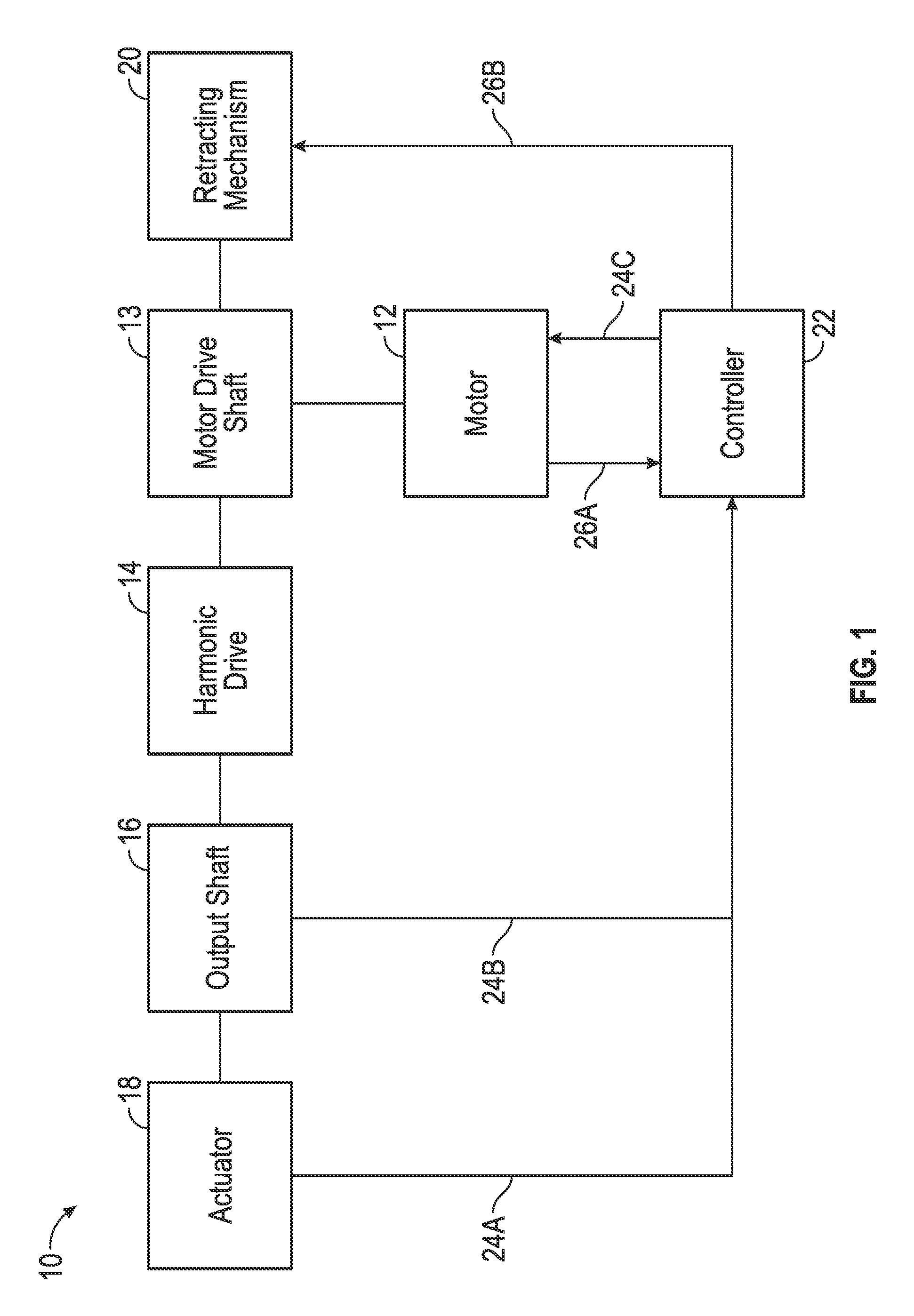
[0015]Referring to FIG. 1, a block diagram of a drive assembly with selective disconnect is illustrated. Drive assembly with selective disconnect 10 includes motor 12, motor drive shaft 13, harmonic drive 14, output shaft 16, actuator 18, retracting mechanism 20, and controller 22. Controller 22 receives feedback signals 24A-24C and gives instruction or command signals 26A and 26B.

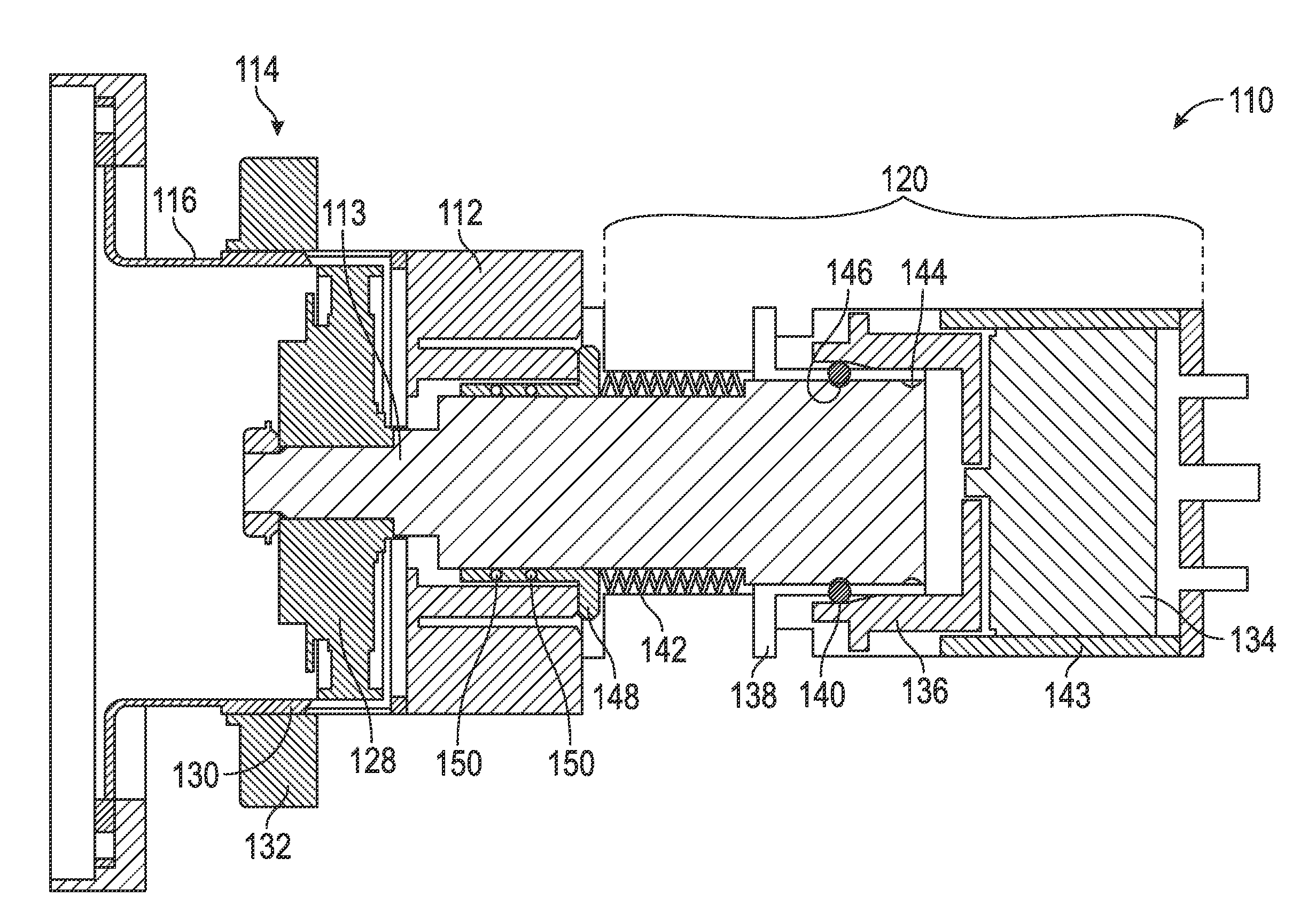
[0016]Motor drive shaft 13 is at least partially within motor 12 and receives energy from motor 12. The energy received by motor drive shaft 13 from motor 12 causes motor drive shaft 13 to rotate. One end of motor drive shaft 13, when in an engaged position (as will be discussed below), is engaged / coupled to harmonic drive 14 which, in turn, is connected / coupled to output shaft 16. Output shaft 16 is connected to and drives actuator 18, which can be used for a variety of purposes, including in an aircraft to control a movable flight control surface, such as an aileron or an elevator. The other end of motor...


PUM


Abstract

A harmonic drive assembly with selective disconnect includes a motor with a motor drive shaft, a harmonic drive operatively coupled to the motor drive shaft, and a wave generator operatively coupled to the motor drive shaft and a flex gear of the harmonic drive. Also included is a ring gear of the harmonic drive operatively coupled to the flex gear with a plurality of ring gear teeth configured to mesh with a plurality of flex gear teeth. Further included is an output shaft operatively coupled to the harmonic drive. Yet further included is a retracting mechanism configured to selectively retract the motor drive shaft and the wave generator to decouple the motor drive shaft and the wave generator from the harmonic drive, wherein a clearance between the ring gear teeth and the flex gear teeth is established upon retraction of the motor drive shaft and the wave generator.

Description

BACKGROUND OF THE INVENTION[0001]The embodiments herein relate to harmonic drives and, more particularly, to a harmonic drive assembly and method for disengaging a harmonic drive.[0002]Aircraft typically include electro-mechanical actuators and other flight control systems that control flight control surfaces on aircraft wing and tail structures. These flight control surfaces are moved and positioned to alter the lift characteristics of the wing and tail structures. For safety, aircraft usually have redundancies in the electro-mechanical actuators and flight control systems that control the flight control surfaces to allow for controlled maneuverability of the aircraft in the event that the primary system malfunctions or fails. When the primary system malfunctions, the backup system takes over and controls the movable flight control surface. The primary system may have become stuck or jammed in one position, making it difficult for the backup system to overcome the primary system an...

Claims


Application Information

Patent Timeline
Patent Type & Authority Patents(United States)
IPC IPC(8): F16H37/04F16D27/14B64C13/42B64C13/34H02K7/116F16H49/00
CPCF16D27/14B64C13/34B64C13/42F16H49/001H02K7/116F16D27/108
Inventor BALSIGER, DERICK S.BLOXHAM, KEITH A.
Owner HAMILTON SUNDSTRAND CORP
Features
  • R&D
  • Intellectual Property
  • Life Sciences
  • Materials
  • Tech Scout
  • Unparalleled Data Quality
  • Higher Quality Content
  • 60% Fewer Hallucinations
Learn More