

Imaging lens
a technology of imaging lens and lens body, applied in the field of imaging lenses, can solve the problems of difficult to provide a low-profile imaging lens with a wide field of view, difficult to correct aberrations in the peripheral area of the image properly, and difficult to achieve effective correction of spherical aberrations and coma aberrations, and achieve optimal refractive power. , the effect of increasing the telephoto capability
- Summary
- Abstract
- Description
- Claims
- Application Information
AI Technical Summary
Benefits of technology
Problems solved by technology
Method used
Image

Examples
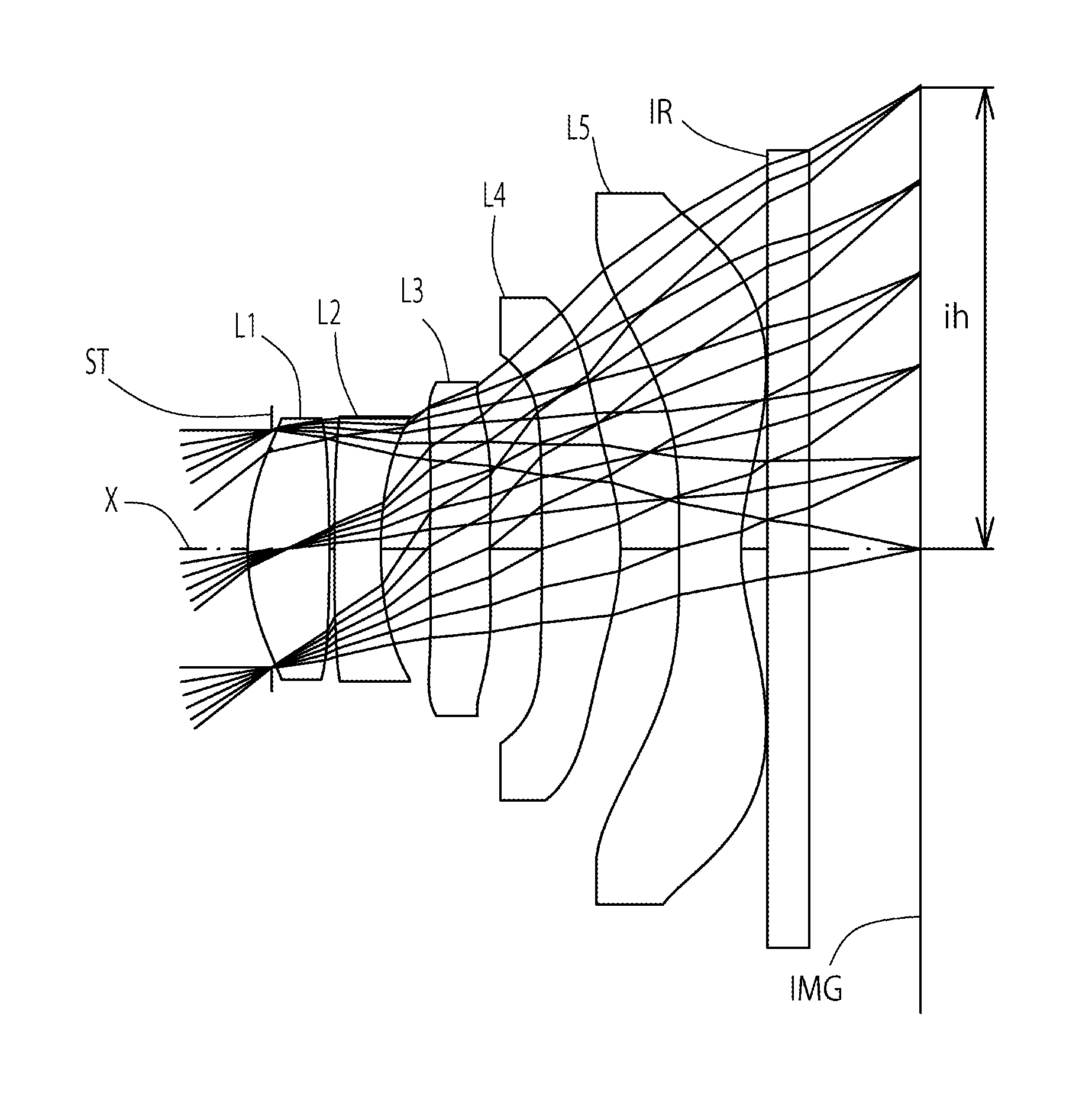
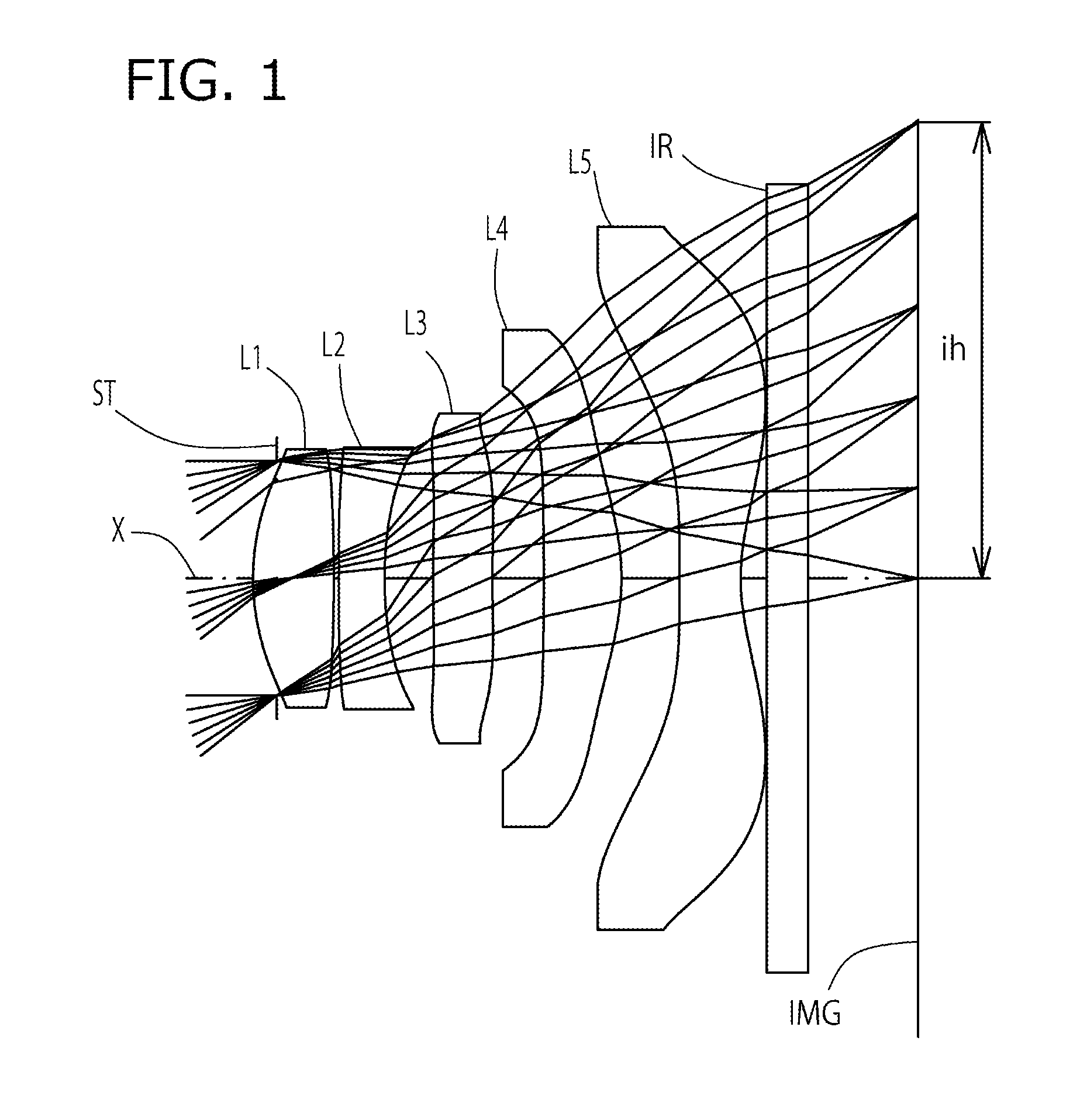
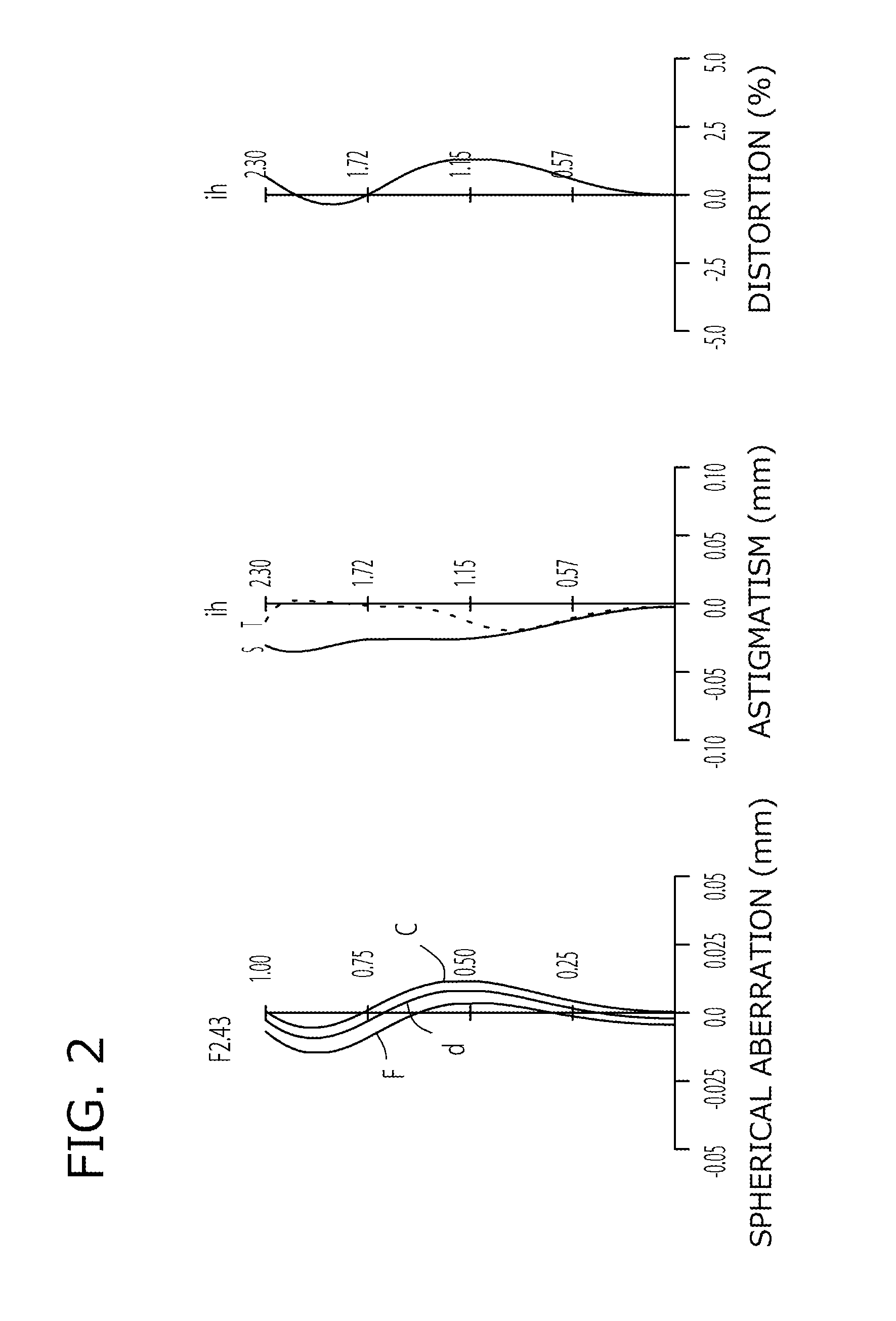
example 1
[0099]The basic lens data of Example 1 is shown in Table 1 below.
[0100]
TABLE 1Example 1in mmf = 2.87Fno = 2.43ω(°) = 38.5ih = 2.30TLA = 3.28bf = 0.82Surface DataCurvatureSurfaceRefractiveAbbeSurface No. iRadius rDistance dIndex NdNumber vd(Object Surface)InfinityInfinity1 Infinity−0.120(Stop)2*1.1940.4071.54455.573*−6.8100.0254*93.0110.2301.63523.975*1.8710.2456*6.3260.2991.54455.577*7.1120.2598*−15.2080.3911.54455.579*−1.1800.29310* −25.4660.3071.53556.1611* 1.0830.13012 Infinity0.2101.51764.2013 Infinity0.552Image PlaneInfinityConstituent Lens DataLensStart SurfaceFocal Length121.90224−3.0103692.764482.329510−1.936Aspheric Surface Data2nd Surface3rd Surface4th Surface5th Surface6th Surfacek0.000E+000.000E+000.000E+005.002E+000.000E+00A4−2.874E−021.756E−011.767E−01−7.087E−02−3.749E−01A6−1.916E−01−3.582E−012.466E−013.872E−012.033E−01A85.894E−01−9.637E−01−2.274E+00−7.482E−013.965E−01A10−1.646E+001.218E+003.332E+003.652E−010.000E+00A120.000E+000.000E+000.000E+000.000E+000.000E+00A140....
example 2
[0105]The basic lens data of Example 2 is shown in Table 3 below.
[0106]
TABLE 3Example 2in mmf = 2.89Fno = 2.45ω(°) = 38.1ih = 2.30TLA = 3.27bf = 0.81Surface DataCurvatureSurfaceRefractiveAbbeSurface No. iRadius rDistance dIndex NdNumber vd(Object Surface)InfinityInfinity1 Infinity−0.120(Stop)2*1.1610.3811.54455.573*−6.2260.0254*98.9060.2301.63523.975*1.8270.2626*12.0120.2861.54455.577*15.7000.2898*−9.8570.3931.54455.579*−1.1890.29210* −15.7560.3071.53556.1611* 1.13610.13012 Infinity0.2101.51764.2013 Infinity0.538Image PlaneInfinityConstituent Lens DataLensStart SurfaceFocal Length121.83324−2.9343691.538482.448510−1.970Aspheric Surface Data2nd Surface3rd Surface4th Surface5th Surface6th Surfacek0.000E+000.000E+000.000E+000.000E+004.868E+00A4−2.823E−021.817E−011.751E−01−7.063E−02−3.843E−01A6−1.912E−01−3.581E−012.621E−013.935E−012.031E−01A85.588E−01−9.972E−01−2.204E+00−7.432E−013.956E−01A10−1.865E+001.179E+003.394E+003.229E−010.000E+00A120.000E+000.000E+000.000E+000.000E+000.000E+00A14...
example 3
[0111]The basic lens data of Example 3 is shown in Table 5 below.
[0112]
TABLE 5Example 3in mmf = 2.87Fno = 2.43ω(°) = 38.4ih = 2.30TLA = 3.28bf = 0.81Surface DataCurvatureSurfaceRefractiveAbbeSurface No. iRadius rDistance dIndex NdNumber vd(Object Surface)InfinityInfinity1 Infinity−0.120(Stop)2*1.2170.3981.54455.573*−11.0260.0254*18.8030.2301.63523.975*1.8950.2446*4.5790.2681.54455.577*5.6120.3188*−13.6520.3661.54455.579*−1.1860.30310* −32.3280.3191.53556.1611* 1.0800.13012 Infinity0.2101.51764.2013 Infinity0.538Image PlaneInfinityConstituent Lens DataLensStart SurfaceFocal Length122.03924−3.3363641.881482.363510−1.948Aspheric Surface Data2nd Surface3rd Surface4th Surface5th Surface6th Surfacek0.000E+000.000E+000.000E+004.884E+000.000E+00A4−2.363E−021.721E−011.735E−01−7.584E−02−3.923E−01A6−1.964E−01−3.654E−012.194E−013.681E−011.870E−01A85.783E−01−9.929E−01−2.366E+00−8.029E−013.952E−01A10−1.515E+009.838E−013.204E+004.585E−010.000E+00A120.000E+000.000E+000.000E+000.000E+000.000E+00A140...
PUM
 Abstract
Description
Claims
Application Information