Musical instrument stand clamp

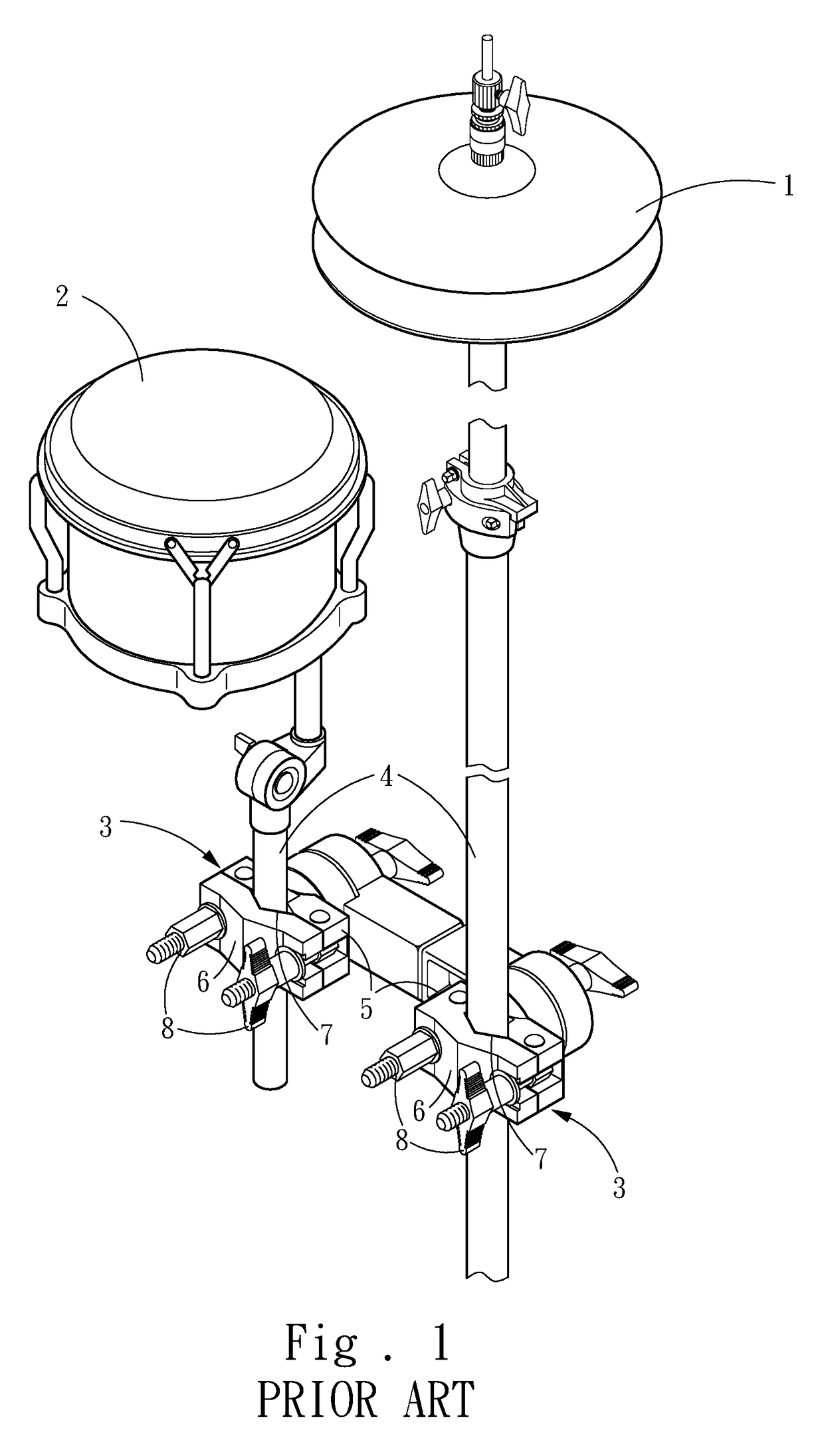
a technology for musical instruments and clamps, which is applied in the direction of instruments, musical supports, fastening means, etc., can solve the problems of the conventional clamp b>3/b> for a musical instrument stand is difficult to meet the requirements of users, and the user may not lock the screws b>8/b> tightly in haste, etc., to achieve the effect of fast assembly or disassembly

Active Publication Date: 2017-04-25
LIAO TSUN CHI
View PDF12 Cites 14 Cited by
  • Summary
  • Abstract
  • Description
  • Claims
  • Application Information

AI Technical Summary

Benefits of technology

[0006]The primary objective of the present invention is to provide a musical instrument stand clamp, whereby the user can assemble or disassemble the musical instrument stand clamp merely via locking or unlocking a single a screw.

Problems solved by technology

Besides, the user may fail to lock the screws 8 tightly in haste.
Therefore, the musical instrument may be damaged while the user disassembles the clamp 3.
Obviously, the conventional clamp 3 for a musical instrument stand is hard to satisfy the requirement of users.

Method used


Image

  • Musical instrument stand clamp
  • Musical instrument stand clamp
  • Musical instrument stand clamp

Examples


Embodiment Construction

[0016]The embodiments will be described in detail in cooperation with the attached drawings to demonstrate the technical contents, characteristics and efficacies of the present invention below.

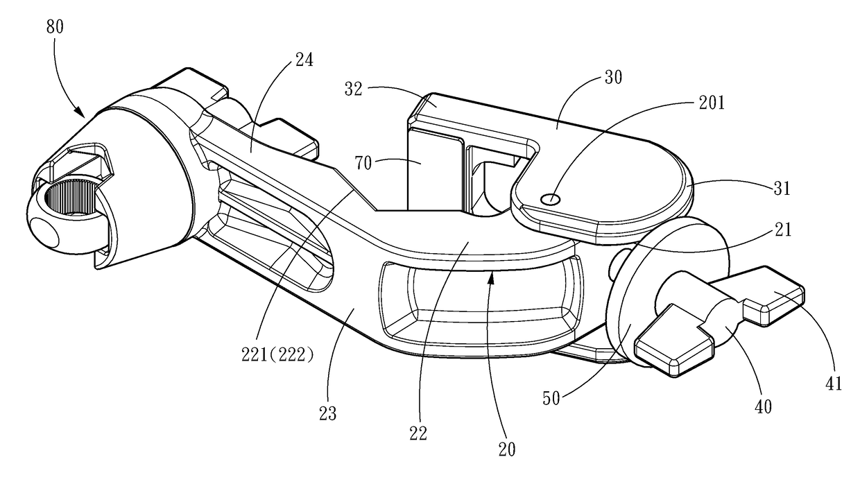
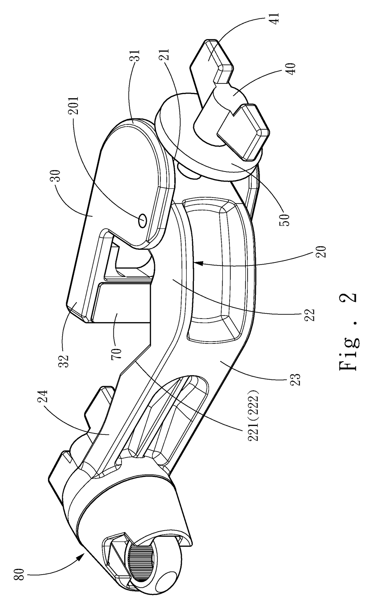
[0017]Refer to FIG. 2, FIG. 3, FIG. 4A, FIG. 4B, and FIG. 5. The musical instrument stand clamp of the present invention is to be fixed to a stand 10 and comprises a fixed part 20, a movable part 30, and a screwing-lock part 40, wherein the movable part 30 is pivotally coupled to a pivotal point 201, and wherein the fixed part 20 includes a locked section 21 and a clamping section 22 respectively at two sides of the pivotal point 201.

[0018]The clamping section 22 includes a clamping member 221. The clamping member 221 includes a fixing groove 222. The movable part 30 includes an outer curved surface 31 near the locked section 21 and a movable member 32 far away from the locked section 21. The screwing-lock part 40 is screwed through the locked section 21 to push the outer curved surface 31 to ...


PUM


Abstract

A musical instrument stand clamp, which to be fixed to a stand, comprises a fixed part, a movable part, and a screwing-lock part. The movable part is pivotally coupled to a pivotal point of the fixed part. The fixed part includes a locked section and a clamping section respectively at two sides of the pivotal point. The movable part includes an outer curved surface near the locked section and a movable member far away from the locked section. The screwing-lock part is screwed through the locked section to push the outer curved surface of the movable part and rotate the movable part with respect to the fixed part so as to move the movable member toward a clamping member of the locked section, whereby the clamp is fixed to the stand. Thus, the clamp can be fast assembled or disassembled merely via rotating the screwing-lock part.

Description

FIELD OF THE INVENTION[0001]The present invention relates to a musical instrument stand clamp, particularly to a fast-assemble / disassemble structure of a musical instrument stand clamp.BACKGROUND OF THE INVENTION[0002]Refer to FIG. 1. A musical instrument, such as a pair of cymbals 1 or a drum 2, is usually fixed to a stand 4 with a clamp 3, whereby they can be arranged around the performer.[0003]The clamp 3 comprises a static plate 5 and a movable plate 6. The static plate 5 and the movable plate 6 respectively include clamp grooves 7. The clamp grooves 7 are corresponding to each other and respectively disposed at two sides of the stand 4. The stand 4 is clamped by the two clamp grooves 7, and two screws 8 are screwed into the static plate 5 and the movable plate 6 respectively from two sides of the stand 4 to lock the static plate 5 and the movable plate 6 together, whereby the clamp 3 is secured to the stand 4.[0004]As shown in FIG. 1, two screws 8 must be screwed into the stati...

Claims


Application Information

Patent Timeline
Patent Type & Authority Patents(United States)
IPC IPC(8): G10D13/02F16B2/10F16B2/06G10G5/00F16M13/02
CPCG10D13/026F16B2/065F16B2/10F16M13/022G10D13/02G10G5/00G10D13/28
Inventor LIAO, TSUN-CHI
Owner LIAO TSUN CHI
Why Eureka
Try Eureka