Supercharge Your Innovation With Domain-Expert AI Agents!

Compact low pressure drop heat exchanger

a heat exchanger and compact technology, applied in indirect heat exchangers, machines/engines, light and heating apparatus, etc., can solve the problems of reduced heat exchange efficiency and malfunction of devices, and achieve the effect of stable structure and enhanced thermal durability

Active Publication Date: 2017-05-02
HANON SYST
View PDF11 Cites 3 Cited by
  • Summary
  • Abstract
  • Description
  • Claims
  • Application Information

AI Technical Summary

Benefits of technology

This design reduces fluid pressure drop by half, decreases overall resistance by four times, and enhances thermal durability and structural stability against temperature changes and external impacts.

Problems solved by technology

When such oil or coolant is increased in temperature, an overflow phenomenon is generated to thereby cause malfunction of the devices.
Since this adversely affects a pumping device for forcibly circulating fluid, heat exchange efficiency may be reduced.

Method used


Image

  • Compact low pressure drop heat exchanger
  • Compact low pressure drop heat exchanger
  • Compact low pressure drop heat exchanger

Examples


Embodiment Construction

[0031]Exemplary embodiments of the present invention will be described below in more detail with reference to the accompanying drawings.

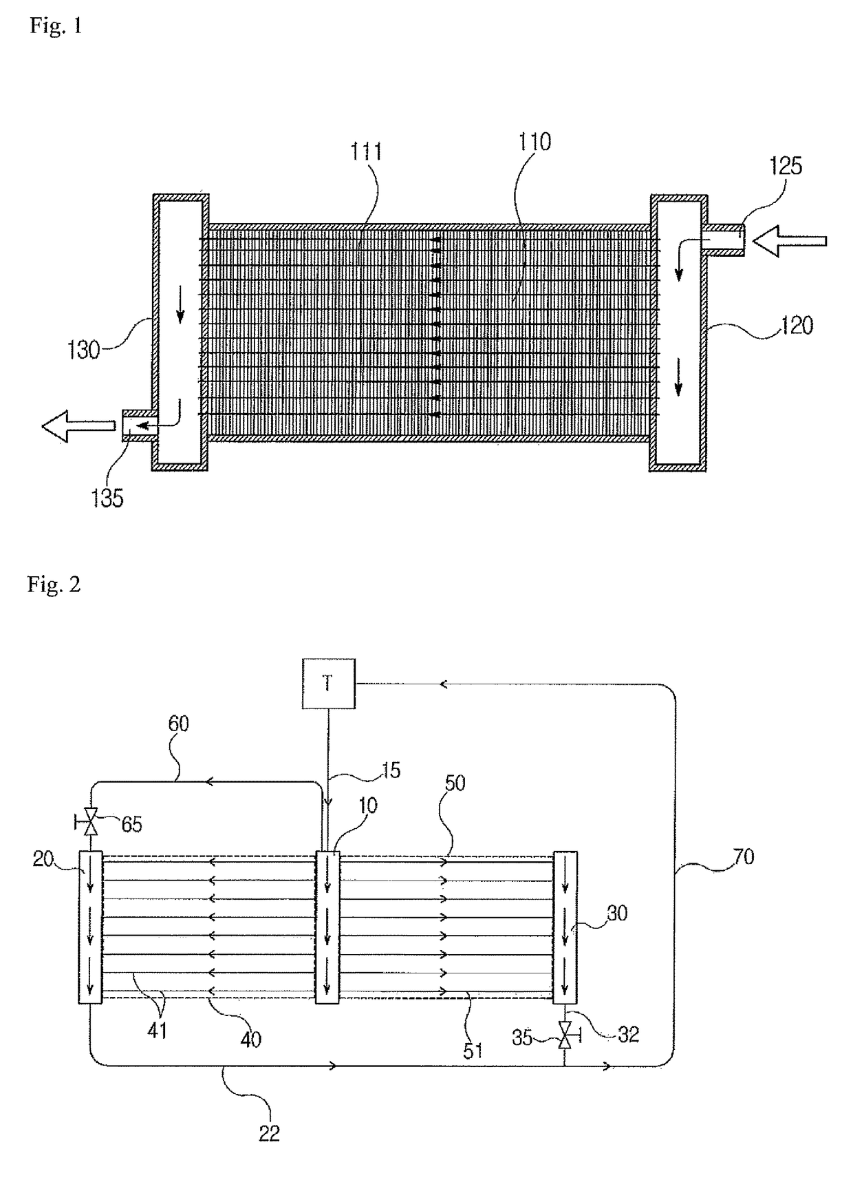
[0032]Although fluid to be cooled used in the present invention includes transmission oil, engine coolant, or hydraulic oil of a variety of hydraulic mechanisms, the transmission oil will be described as an example in the following embodiment.

[0033]Referring to FIGS. 2 and 3, a heat exchanger in a vehicle according to an embodiment of the present invention includes a supply manifold 10 which supplies fluid introduced from a transmission while distributing the fluid to first and second cooling units 40 and 50. The first cooling unit 40 cools the fluid supplied from the supply manifold 10 by heat exchange action. A first return manifold 20 collects and discharges the fluid discharged from the first cooling unit 40. The second cooling unit 50 cools the fluid supplied from the supply manifold 10 by heat exchange action. A second return manifold 30 colle...


PUM


Abstract

Disclosed herein is a heat exchanger in a vehicle including a supply manifold which supplies fluid introduced from the outside while distributing the fluid to first and second cooling units. The first and second cooling units cool the fluid supplied from the supply manifold by heat exchange action. A first return manifold collects and discharges the fluid discharged from the first cooling unit and a second return manifold collects and discharges the fluid discharged from the second cooling unit.

Description

CROSS-REFERENCE TO RELATED APPLICATIONS[0001]This application claims priority to U.S. provisional Application No. 61 / 887,582, filed on Oct. 7, 2013, the disclosure of which is incorporated herein by reference in its entirety.FIELD OF THE INVENTION[0002]Exemplary embodiments of the present invention relate to a heat exchanger in a vehicle, and more particularly, to a heat exchanger in a vehicle, which cools engine coolant or transmission oil of a vehicle, or hydraulic oil.BACKGROUND OF THE INVENTION[0003]In general, a transmission in a vehicle is supplied with oil in order to lubricate rotary bodies such as a torque converter, a gear, and a bearing. Hydraulic oil is used for a variety of hydraulic mechanisms such as a clutch and a brake. Coolant is used to cool an engine.[0004]When such oil or coolant is increased in temperature, an overflow phenomenon is generated to thereby cause malfunction of the devices. Therefore, a cooler or a heat exchanger is used to maintain the temperature...

Claims


Application Information

Patent Timeline
Patent Type & Authority Patents(United States)
IPC IPC(8): F28D1/053F28F9/26F28F27/02F28D21/00F01P3/18
CPCF28D1/05316F28F9/262F28F27/02F01P2003/185F28D2021/0089F28D2021/0094F28F2250/06
Inventor DZIUBINSCHI, OREST ALEXANDRUSHASKA, KASTRIOTCARDWELL, BRIAN JAMES
Owner HANON SYST
Features
  • R&D
  • Intellectual Property
  • Life Sciences
  • Materials
  • Tech Scout
  • Unparalleled Data Quality
  • Higher Quality Content
  • 60% Fewer Hallucinations
Learn More