AI technical title is built by Patsnap AI team. It summarizes the technical point description of the patent document.
a technology of ink jet printers and ink jet heads, applied in printing and other directions, can solve problems such as density unevenness in printed images
Active Publication Date: 2018-04-24
BROTHER KOGYO KK
View PDF24 Cites 4 Cited by
Summary
Abstract
Description
Claims
Application Information
AI Technical Summary
This helps you quickly interpret patents by identifying the three key elements:
Problems solved by technology
Method used
Benefits of technology
Benefits of technology
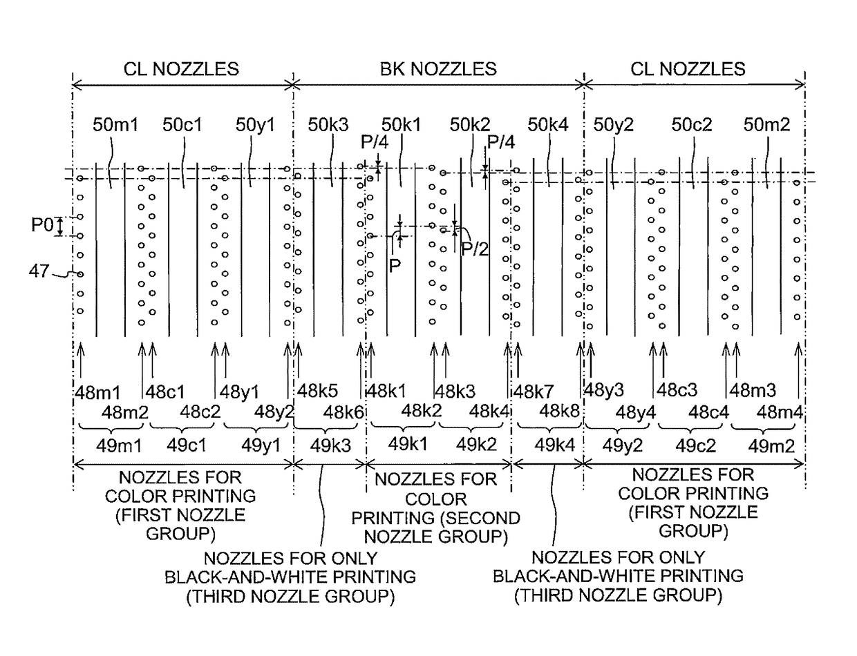
[0009]It is an object of the present teaching to suppress the difference of amount of ink jetted (hereinafter referred to as “ink jet amount”) to a low level between two types of nozzle groups which jet the same type of ink but differ in jet frequency,
[0023]In this regard according to the present teaching, however, first, the two third nozzle groups are arranged separately in the first direction and, two groups selected from the first and second nozzle groups are arranged on the two opposite sides of each of the third nozzle groups. That is, each of the third nozzle groups is arranged to be interposed between two of the first and second nozzle groups. By virtue of this, even in the case of the first printing process using the first nozzle groups and the second nozzle groups but not using the third nozzle groups, the ink temperature also increases in the third nozzle groups interposed between the first nozzle groups and the second nozzle groups in which the ink temperatures increase respectively. By virtue of this, the difference in ink temperature is reduced between the second nozzle groups and the third nozzle groups when starting the second printing process, thereby suppressing the density unevenness in images.
Problems solved by technology
This difference in the ink jet amount causes density unevenness to occur in printed images.
Method used
Image
Click on the blue label to locate the original text in one second.
Reading with bidirectional positioning of images and text.
Examples
first embodiment
[0045]Next, the present teaching will be explained.
[0046](A Schematic Configuration of a Printer)
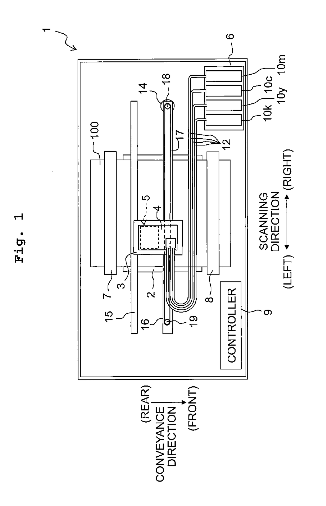
[0047]As depicted in FIG. 1, a printer 1 includes a platen 2, a carriage 3, a sub-tank 4, an ink jet head 5, a holder 6, a paper feed roller 7, a paper discharge roller 8, a controller 9, and the like. Further, hereinbelow, the near side of the page of FIG. 1 will be defined as “upper side” or “upside” of the printer 1 while the far side of the page will be defined as “lower side” or “downside” of the printer 1. Further, the front-rear direction and left-right direction depicted in FIG. 1 are defined as the “front-rear direction” and “left-right direction” of the printer 1, respectively.
[0048]On the upper surface of the platen 2, there is carried a sheet of recording paper 100 which is a recording medium, Further, two guide rails 15 and 16 are provided above the platen 2 to extend parallel to the left-right direction of FIG. 1 (to be also referred to as a scanning direction).
[0049]The ca...
second embodiment
[0124]That is, in the second embodiment, the outer nozzle row 68y1 of the second head unit 61b, the outer nozzle row 68y2 of the third head unit 61c, the nozzle rows 68c2 and 68m1 of the fourth head unit 61d, and the nozzle rows 68c1 and 68c2 of the fifth head unit 61e correspond respectively to the “first nozzle groups” of the present teaching. The nozzle rows 68k1 and 68k2 of the first head unit 61a, which are used simultaneously with the nozzle rows 68y, 68c and 68m for color in the full color print, correspond to the “second nozzle groups” of the present teaching. Further, the inner nozzle row 68k4 of the second head unit 61b and the inner nozzle row 68k3 of the third head unit 61c, which are not used simultaneously with the nozzle rows 68y, 68c and 68m for the color inks, correspond to the “third nozzle groups” of the present teaching.
[0125]As described above, the second head unit 61b and the third head unit 61c are dislocated respectively by P / 4 in the conveyance direction, wi...
PUM
Abstract
There is provided an ink jet printer including a carriage, and an ink jet head. The ink jet head has two first nozzle groups to jet a first ink, two second nozzle groups to jet a second ink, and two third nozzle groups to jet the second ink. Each of the first, second and third nozzle groups includes a plurality of nozzles arrayed at a pitch P along a second direction. The second nozzle groups accord respectively with the first nozzle groups in terms of nozzle position in the second direction, the third nozzle groups are dislocated respectively from the second nozzle groups in terms of nozzle position in the second direction, and any two groups selected from the first and second nozzle groups are arranged respectively on two opposite sides of each of the third nozzle groups in the first direction.
Description
CROSS REFERENCE TO RELATED APPLICATION[0001]The present application claims priority from Japanese Patent Application No. 2015-073701, filed on Mar. 31, 2015, the disclosure of which is incorporated herein by reference in its entirety.FIELD OF THE INVENTION[0002]The present invention relates to ink jet printers and ink jet heads.DESCRIPTION OF THE RELATED ART[0003]Conventionally, there are known ink jet printers applying such a method as to print image and the like by jetting ink from respective nozzles toward a recording medium while moving an ink jet head having the plurality of nozzles in a predetermined scanning direction. There are known ink jet heads used in such ink jet printers to have four types of nozzle rows jetting inks of four colors: black (K), cyan (C), magenta (M), and yellow (Y). For example, two nozzle rows are provided for the ink of one color such that there are eight nozzle rows in total for the four colors.[0004]Further, there is known an ink jet head in which t...
Claims
Application Information
Patent Timeline
Application Date:The date an application was filed.
Publication Date:The date a patent or application was officially published.
First Publication Date:The earliest publication date of a patent with the same application number.
Issue Date:Publication date of the patent grant document.
PCT Entry Date:The Entry date of PCT National Phase.
Estimated Expiry Date:The statutory expiry date of a patent right according to the Patent Law, and it is the longest term of protection that the patent right can achieve without the termination of the patent right due to other reasons(Term extension factor has been taken into account ).
Invalid Date:Actual expiry date is based on effective date or publication date of legal transaction data of invalid patent.

