

Print control device and program
a control device and control device technology, applied in printing, other printing apparatus, etc., can solve the problems of difficult to suppress density irregularities, easy degradation of quality of printed images, and thereby deterioration of printed images, etc., and achieve the effect of density irregularities
- Summary
- Abstract
- Description
- Claims
- Application Information
AI Technical Summary
Benefits of technology
Problems solved by technology
Method used
Image

Examples
first embodiment
Overall Configuration
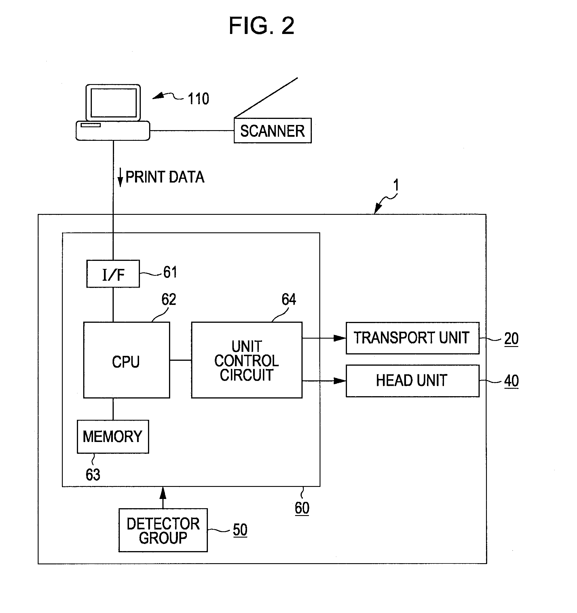
[0055]In the present embodiment, an image is printed using an ink jet printer (printer 1) as a printing apparatus. FIG. 2 is a block diagram showing an overall configuration of the printer 1. FIG. 3 is a schematic side view of the printer 1.
[0056]A computer 110 is connected to the printer 1 and a scanner that is an image reading device if necessary. In the computer 110, a printer driver is installed. The printer driver performs a process causes print data to be generated in the computer 110, transmits this print data to the printer 1 so as to cause the printer 1 to print an image. In other words, in the present embodiment, the computer 110 in which the printer driver is installed is a print control device.
[0057]In addition, a scanner driver is installed in the computer 110. The scanner driver can cause the scanner 120 to read a document set in the scanner 120, and thereby acquiring image data from the scanner 120.
[0058]The printer 1 has a transport unit 20, a he...
embodiment
Effect of Embodiment
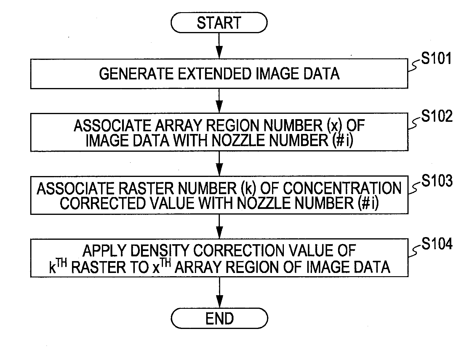
[0118]In the present embodiment, when the raster numbers of the density correction values and the nozzle numbers are associated, the test patterns printed based on the array reference using nozzles including overlapping portions of two nozzle arrays and rules printed adjacent to the test patterns are used. The density correction values of each of the raster lines are computed from the density of each of the raster lines of the test patterns. Then, the positions of the nozzles included in each head are respectively specified from the positions of the rules, and associated with the positions of the raster lines for which the density correction values are computed. Accordingly, with reference to the positions of the rules, the density correction values of each of the raster lines can be accurately associated with the positions of the nozzles of each head, and thus, density irregularity occurring when inks are discharged from the nozzles can be effectively suppressed...
modification example 1
[0119]A modification example (Modification Example 1) of test patterns and rules printed in the process of associating density correction values for each array region and each nozzle (S103) will be described.
[0120]FIG. 18 is a diagram showing test patterns in Modification Example 1. The test patterns themselves are the same as that described in FIG. 14, but the rule part is different. In Modification Example 1, rules A are printed by the head 42A, and rules B are printed by the head 42B. Then, in the portion other than the overlapping region of the two heads, density correction values and raster numbers (k) thereof, and nozzle numbers (#i) of each head are associated in the same method as in the process 5135 described above. On the other hand, in the overlapping region, the raster number are separately associated with the nozzle numbers for each head.
[0121]FIG. 19 is a diagram describing association of raster numbers of density correction values and nozzle numbers when rules are pri...
PUM
 Abstract
Description
Claims
Application Information