Ignition Element Mounting Capacitor, Header Assembly, Squib and Gas Generator for Air Bag and Gas Generator for Seat Belt Pretensioner

a technology for mounting capacitors and ignition elements, which is applied in pedestrian/occupant safety arrangements, electrical fuzes, lighting and heating apparatuses, etc., and can solve problems such as increased risk of erroneous explosion caused by noise and high possibility of bonding wires connected to ignition elements

Active Publication Date: 2010-03-25
NIPPON KAYAKU CO LTD +2
View PDF2 Cites 6 Cited by
  • Summary
  • Abstract
  • Description
  • Claims
  • Application Information

AI Technical Summary

Benefits of technology

[0040]Effects of the invention can be enumerated as follows.(1) According to the invention only one capacitor performs the functions of two kinds of capacitors, that is, the capacitor for ignition and the bypass capacitor for driving the IC and removing the noise, thereby achieving the miniaturization of the squib.(2) As the construction is employed that the ignition element is mounted on the capacitor described above, the squib can be more miniaturized.(3) As the ignition element is connected to the IC through the third external terminal electrodes provided on the capacitor, the ignition element on the uppermost surface and the IC on the lowermost surface can be electrically connected without using the wire bonding, and a high ignition reliability can be obtained because there is no wire bonding at the contact surface with the ignition powder.(4) By locating the bypass capacitor immediately on the IC, the noise reducing effect can be obtained in an ideal condition.(5) The capacitor for ignition is located immediately on the IC and the ignition element is located immediately on the capacitor for ignition so that the ignition element is connected to the IC through the third external terminal electrodes, with the result that the flow passage of the electrical current flowing through the ignition element becomes very short when the switching circuit in the IC is switched on. Therefore, inductance components become little to reduce losses so that sharp discharge waveforms from the capacitor can be transmitted to the ignition element without modification of the waveforms, with the result that the ignition reliability is remarkably improved.(6) The respective parts are laid on the header and the contact surface with the ignition powder is flattened by a resin so that irregularities in density of the ignition powder upon the ignition element being pushed to the ignition powder are eliminated and the compact header assembly can be constructed. Moreover, as the ignition powder is securely insulated from the respective electrodes, erroneous ignition of the ignition means can be prevented.(7) As the ceramic capacitor is used as the capacitor, the electrodes can be arranged within a size enabling direct mounting on the IC, and at the same time great electrostatic capacitances can be held, thereby enabling a miniaturization and an improvement in ignition reliability.

Problems solved by technology

The first problem is the fact that the second small semiconductor plate (ignition element) and the third small semiconductor plate (IC) are connected by bonding wires.
Upon applying such a great pushing force, there would be a high possibility of breaking of the bonding wires connected to the ignition element.
The second problem is the fact that a semiconductor capacitor is used as an energy-storing capacitor for ignition.
In this case, however, the ignition sensibility is so high that the risk of erroneous explosion caused by noise would be increased.

Method used


Image

  • Ignition Element Mounting Capacitor, Header Assembly, Squib and Gas Generator for Air Bag and Gas Generator for Seat Belt Pretensioner
  • Ignition Element Mounting Capacitor, Header Assembly, Squib and Gas Generator for Air Bag and Gas Generator for Seat Belt Pretensioner
  • Ignition Element Mounting Capacitor, Header Assembly, Squib and Gas Generator for Air Bag and Gas Generator for Seat Belt Pretensioner

Examples


Embodiment Construction

[0106]The invention will then be specifically explained.

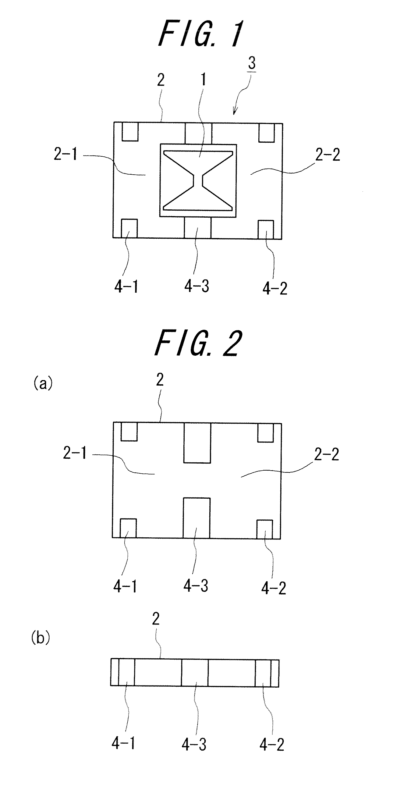
[0107]FIG. 1 illustrates a preferable example of the ignition element mounting capacitor according to the invention in a plan view. In addition, FIG. 2 shows the capacitor only in a plan view (a) and a side view (b).

[0108]In FIG. 1, reference numeral 1 denotes an ignition element, and reference numeral 2 shows a capacitor body having two kinds of capacitor functions. The ignition element 1 is mounted on the capacitor body 2 to construct the ignition element mounting capacitor 3.

[0109]The capacitor body 2 is constructed by laminating a plurality of dielectric layers and has therein a first capacitor section 2-1, and a second capacitor section 2-2. The first capacitor section is used for igniting, while the second capacitor section is for activating an IC or removing noise.

[0110]Moreover, the capacitor body 2 is provided on its outer surfaces with first to third external terminal electrodes 4-1, 4-2, and 4-3. The first external t...


PUM

PropertyMeasurementUnit
electric currentaaaaaaaaaa
thicknessaaaaaaaaaa
thicknessaaaaaaaaaa

Abstract

An ignition element mounting capacitor having an ignition element mounted on a capacitor, includes therein a first capacitor section and a second capacitor section, and first external terminal electrodes electrically connected to the first capacitor section and second external terminal electrodes electrically connected to the second capacitor section. The first capacitor section has a capacity for igniting ignition powder, and the second capacitor section has a function for removing noise which affects external circuits. Further, provided on the surface of the capacitor are third external terminal electrodes electrically connected to the ignition element. In this manner, the invention provides a squib enabling its size to be miniaturized and its quality to be improved, while keeping a high productivity, and hence provides a header assembly and a ignition element mounting capacitor as components of the squib and further provides a gas generator having such a squib installed therein for an air bag and a gas generator having the squib for a seat belt pretensioner.

Description

TECHNICAL FIELD[0001]This invention relates to a squib to be installed in a gas generator or the like used in a safety device for a car such as an air bag and the like. Moreover, this invention relates to a header assembly which is a component of the squib described above, and an ignition element mounting capacitor to be built in the header assembly.[0002]Further, this invention relates to a gas generator with such a squib installed therein for an air bag, and a gas generator with the squib for a seat belt pretensioner.BACKGROUND ART[0003]A various kinds of electric squibs have been developed as squibs for gas generators for inflating air bags equipped in cars. Such a squib usually has metal pins for electrically connecting to the external, and a heating element at the other ends of the metal pins for igniting an explosive.[0004]With hitherto used ignition devices, bridging wires have been used for igniting ignition powder. Nichrome wires have been used as bridging wires. If wire di...

Claims


Application Information

Patent Timeline
Patent Type & Authority Applications(United States)
IPC IPC(8): B60R21/26F42B3/10F42B3/13F42C19/12F42B3/04F42B3/103B60R22/46B01J7/00B60R21/264H01G4/12
CPCB60R2021/26029F42B3/18F42B3/13F42B3/121
Inventor MAEDA, SHIGERUISHIDA, ATSUSHINAKANISHI, KATSUKIKOSHIDO, YOSHIHIROYAMADA, HAJIMEAIZAWA, NAOKOMATSUMURA, YASUAKIFURUYA, TOSHIAKI
Owner NIPPON KAYAKU CO LTD
Why Eureka
Try Eureka