Pipe type circulation-based reaction apparatus

A technology of reaction device and tube type, applied in feeding device, chemical/physical/physical-chemical fixed reactor, chemical/physical/physical-chemical reactor, etc. The effect of suppressing the reduction of the generation rate, suppressing the concentration variation, and increasing the contact area

Inactive Publication Date: 2013-02-06
NISSO ENG
View PDF7 Cites 3 Cited by
  • Summary
  • Abstract
  • Description
  • Claims
  • Application Information

AI Technical Summary

Problems solved by technology

In the reaction device of Patent Document 3, precipitation occurs at the center of the vortex generated in the mixing reaction tube, which causes a decrease in the production rate of the reaction product due to concentration unevenness

Method used


Image

  • Pipe type circulation-based reaction apparatus
  • Pipe type circulation-based reaction apparatus
  • Pipe type circulation-based reaction apparatus

Examples


no. 1 approach )

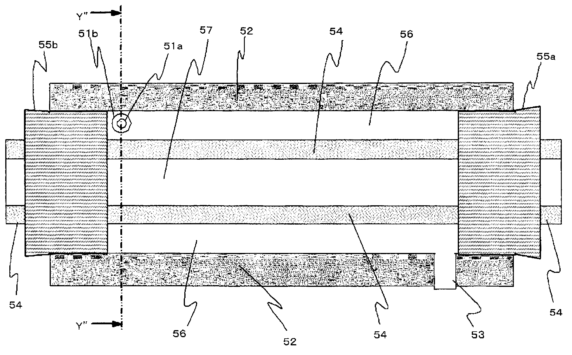
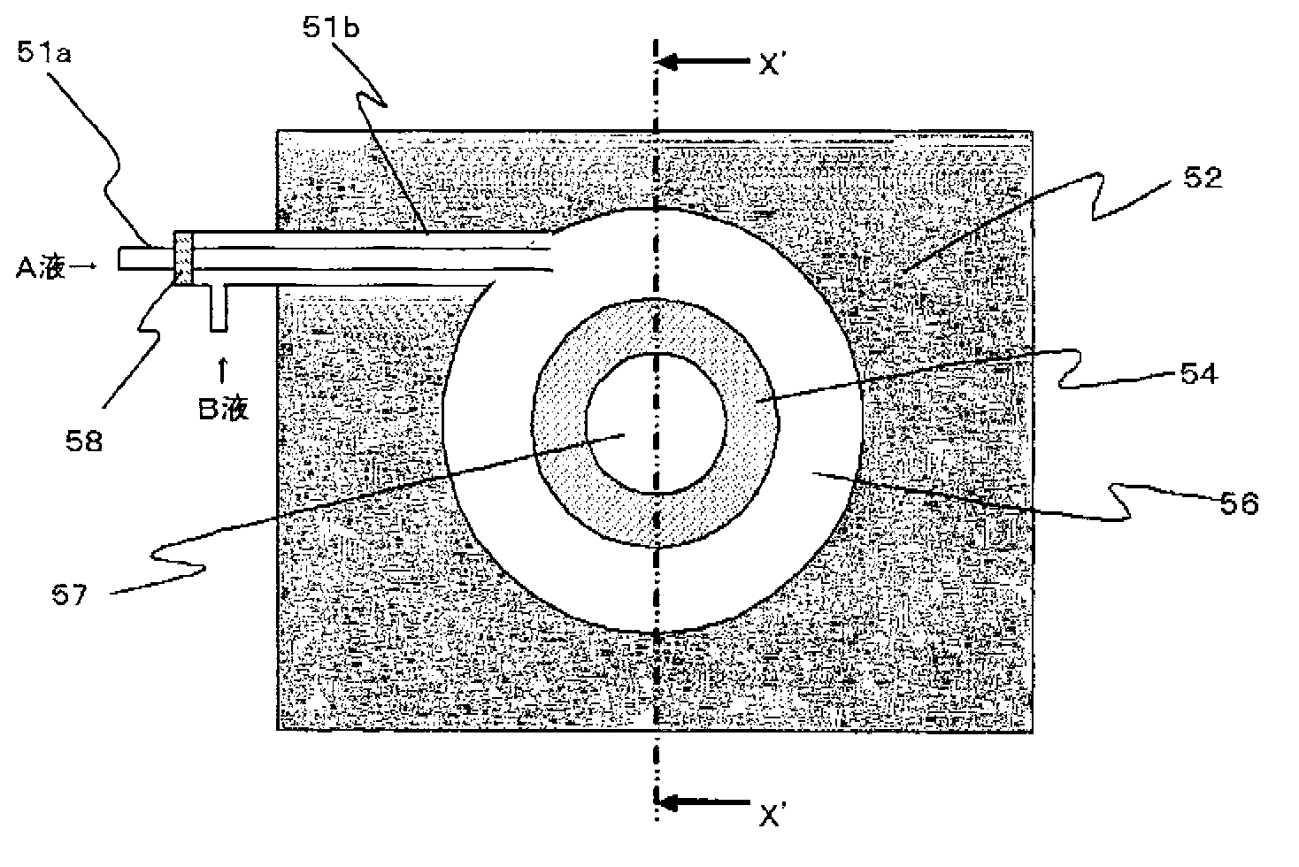
[0049] figure 1 It is an X' arrow view of one embodiment of the tubular flow-through reactor of the present invention. figure 2 yes figure 1 The Y" view of the tubular flow-through reaction device shown.

[0050] figure 1 The shown reaction device of the present invention has a double tube structure composed of an outer cylinder member 52 and a core member 54 . in addition, figure 1 The shown device has a double tube structure, however, if necessary, further tubes may be provided on the outside of the outer cylinder member 52 to have a triple tube structure. exist figure 1 In the illustrated embodiment, the outer cylinder member 52 is formed by perforating polygonal columns to form an inner cavity through which fluid can flow, but the present invention is not limited thereto. For example, a straight pipe may be used, or a flat plate may be excavated to form a groove, and a cover may be placed there to form a cavity through which a fluid can flow. In addition, in figur...

no. 2 approach )

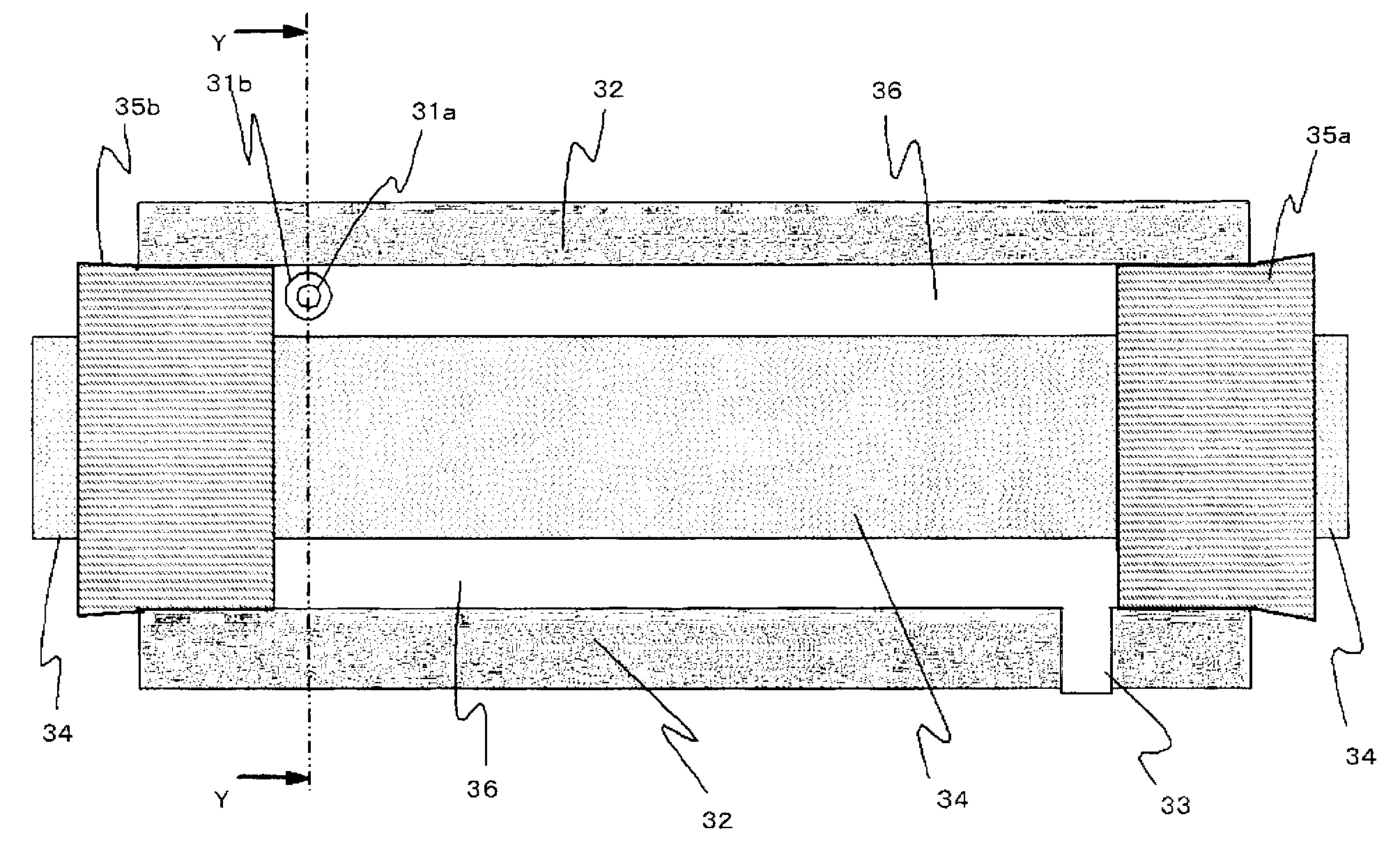
[0071] image 3It is an X-direction view of the second embodiment of the tubular flow reaction device of the present invention. Figure 4 yes image 3 Y-direction view of the tubular flow-through reactor shown. Such as image 3 and Figure 4 The illustrated tubular flow-through reactor has the same structure as that of the first embodiment except that the core member and the circular tube 54 are replaced with the column 34 .

no. 3 approach )

[0073] Figure 5 It is a Z' view of the third embodiment of the tubular flow-through reactor of the present invention. Figure 6 yes Figure 5 The y' view of the tubular flow-through reactor shown. Such as Figure 5 and Figure 6 In the illustrated tubular flow-through reactor, the fluid supply channels are connected in a direction substantially perpendicular to the peripheral surface. In addition, in the present invention, the so-called substantially orthogonal or substantially right angle is 90°±45°. When the connection is made in a direction substantially perpendicular to the peripheral surface, the supplied fluid collides with the core member and spreads to the left and right of the annular reaction channel, resulting in complicated convection.


PUM


Abstract

Disclosed is a pipe type circulation-based reaction apparatus which comprises two or more fluid supply passages formed by a multi-layered tube for supplying two or more types of fluids to be used for reaction; a reaction flow passage which has an annular cross section and is capable of reacting said fluids while causing the same to circulate; and a fluid discharge passage for discharging resection products. In order that the fluid supply passages may communicate with the inlet to the reaction flow passage, the fluid supply passages are connected along a circumferential tangent direction of the annular reaction flow passage or along a direction intersecting the circumferential surface thereof at right angles. Furthermore, the fluid discharge passage is connected to the outlet of the reaction flow passage in such a way as to establish communication.

Description

technical field [0001] The invention relates to a tubular flow-through reaction device. More specifically, the present invention relates to a tube-type flow-through reactor that increases the contact area between reaction substrates immediately after merging and suppresses a reduction in the production rate of reaction products due to concentration variations. Background technique [0002] In recent years, as flow-through reactors for reacting liquids such as reagents, micro-sized and millimeter-sized reactors, for example, have been developed. [0003] As the simplest form of the microreactor, a T-type or Y-type reactor can be cited. In this reactor, T-shaped or Y-shaped grooves with a depth of 40 μm and a width of 100 μm were engraved on a plate, and a cover was made of a flat plate and connected to a tube. One is opened at the end of each T or Y on the plate to be the cover, for a total of three holes. Two kinds of reaction substrates are put into the left and right si...

Claims


Application Information

Patent Timeline
Patent Type & Authority Applications(China)
IPC IPC(8): B01J19/24B01F5/00
CPCB01F15/066B01J19/0013B01J19/244B01F15/0202B01F2015/061B01J2219/0286B01F5/0057B01J2219/00094B01J2219/029B01J19/0093B01J2219/00788B01J2219/00797B01J2219/00889B01J4/002B01J2219/00894B01F25/10B01F33/30B01F35/711B01F2035/98B01F35/93B01J19/2415B01J19/24B01F25/00
Inventor 小林英一郎
Owner NISSO ENG
Why Eureka
Try Eureka