Heater element for a vaporization device

a heating element and vaporization device technology, applied in lighting and heating apparatus, tobacco, container discharging methods, etc., can solve the problems of affecting affecting the user, and affecting the user, so as to reduce the surface roughness of the heating element, reduce the operation of the device, and heat up extremely quickly

Active Publication Date: 2018-06-12
FUNAI ELECTRIC CO LTD
View PDF10 Cites 1 Cited by
  • Summary
  • Abstract
  • Description
  • Claims
  • Application Information

AI Technical Summary

Benefits of technology

[0001]One of the applications of a fluidic ejection device is to jet a solution onto to another device where a secondary function may be performed. A common secondary function is to vaporize a solution using a heater such that the contents of the solution can be vaporized so as to deliver the solution as a gaseous substance. Applications of such technology include, but are not limited to, metering and vaporizing device for electronic cigarettes, vapor therapy, gaseous pharmaceutical delivery, vapor phase reactions for micro-labs, and the like. A problem associated with such devices is efficient vaporization of the fluid. This document discloses improved heating elements and methods for improving the vaporization efficiency of heating elements for vaporization devices.

Problems solved by technology

The problem lies in that the vaporizing heater must be small enough to heat up extremely quickly, but yet has enough surface area to catch all fluid and fluid droplets that are being ejected onto the heating element.
In some applications, the discharge of liquid is not only undesirable, but may be detrimental to the user.
Also, unvaporized fluid may build up inside the vaporization device and thus degrade the operation of the device.

Method used


Image

  • Heater element for a vaporization device
  • Heater element for a vaporization device
  • Heater element for a vaporization device

Examples


Embodiment Construction

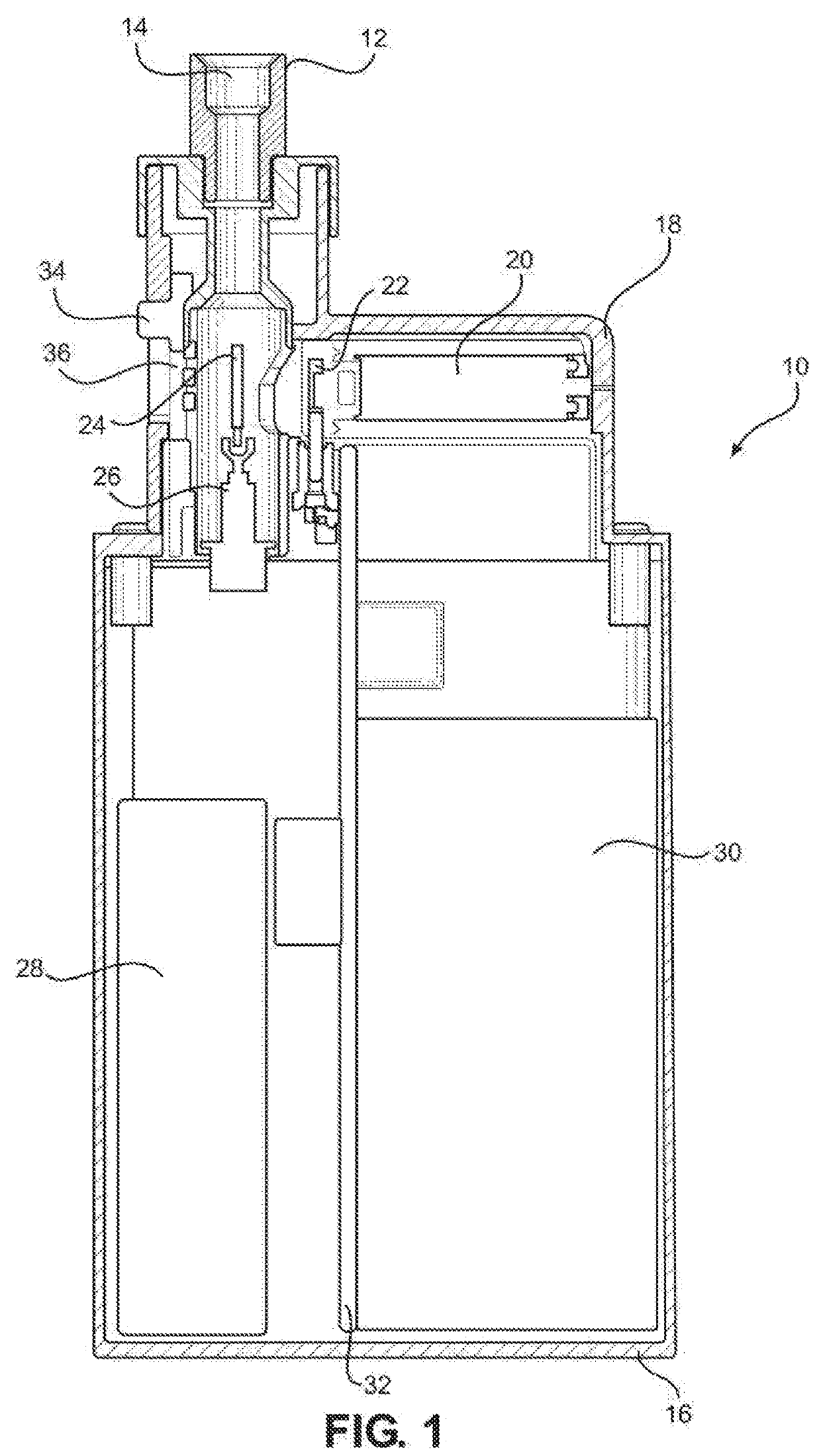
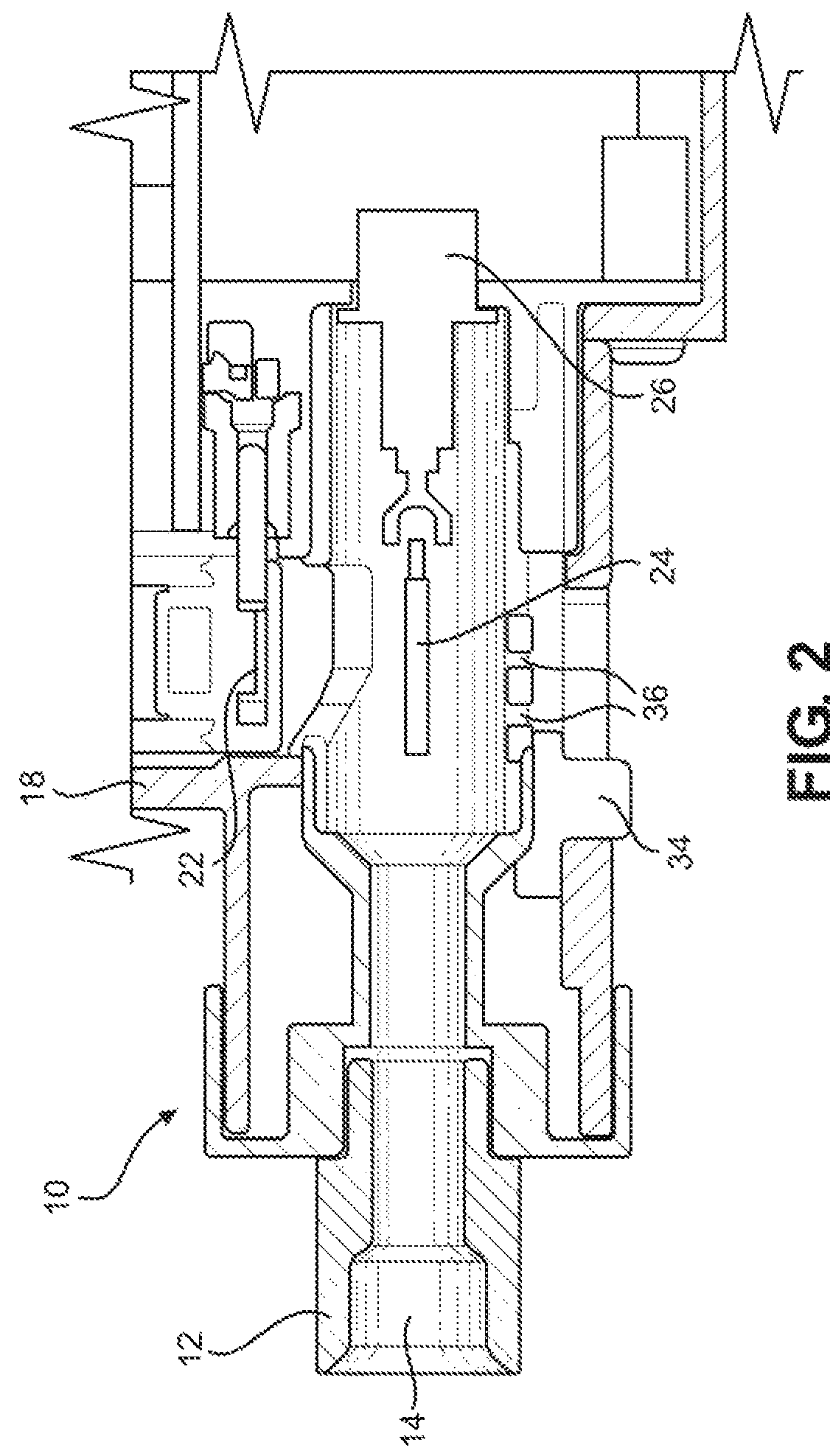
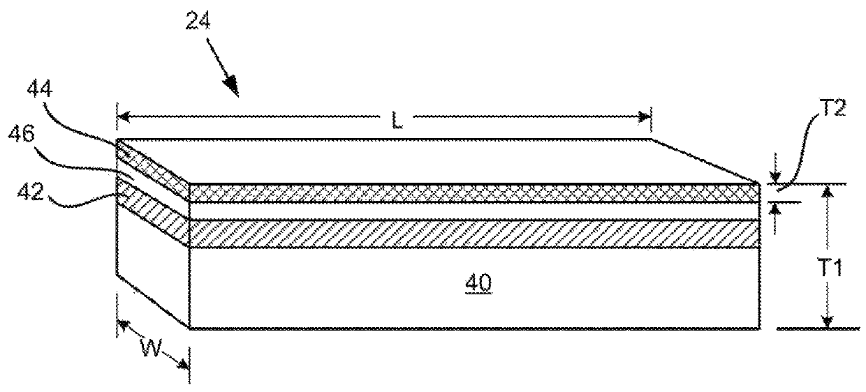
[0023]The disclosure is directed to a vaporization device 10 as shown in FIGS. 1 and 2 and heating elements therefor as shown in FIGS. 3-8. Such devices 10 may be used for a wide variety of applications wherein a liquid is ejected onto a heating element to provide a vapor stream as described in more detail below. Such devices 10 are typically hand held devices such as electronic cigarettes that have a mouthpiece 12 for inhaling vapors generated by the device 10. The mouthpiece 12 includes a conduit 14 for flow of vapors out of the device 10. The main components of the device 10 include a housing body 16, a removable cartridge cover 18, a removable fluid supply cartridge 20, an ejection head 22 associated with the fluid supply cartridge 20, and a heating element 24 and holder therefor 26 for vaporizing fluid ejected from the ejection head 22. Other components associated with the vaporization device 10 include a rechargeable power supply 28, a main circuit board 30, and a vaporization...


PUM

PropertyMeasurementUnit
porosityaaaaaaaaaa
thicknessaaaaaaaaaa
thicknessaaaaaaaaaa

Abstract

A heating element for a vaporizing device, a vaporizing device containing the heating element, and a method for vaporizing fluid ejected by an ejection head. The heating element includes a conductive material deposited onto an insulative substrate, a protective layer deposited onto the conductive layer, and a porous layer having a porosity of at least about 50% deposited onto the protective layer. The heating element has an effective surface area (ESA) for fluid vaporization that is greater than a planar surface area defined by dimensions of the heating element so that a fluid contact surface of the heating element is greater than the planar surface area of the heating element.

Description

TECHNICAL FIELD[0001]One of the applications of a fluidic ejection device is to jet a solution onto to another device where a secondary function may be performed. A common secondary function is to vaporize a solution using a heater such that the contents of the solution can be vaporized so as to deliver the solution as a gaseous substance. Applications of such technology include, but are not limited to, metering and vaporizing device for electronic cigarettes, vapor therapy, gaseous pharmaceutical delivery, vapor phase reactions for micro-labs, and the like. A problem associated with such devices is efficient vaporization of the fluid. This document discloses improved heating elements and methods for improving the vaporization efficiency of heating elements for vaporization devices.BACKGROUND AND SUMMARY[0002]When jetting a fluid onto a heated surface it is highly desirable for 100% of the fluid to vaporize so that liquid is not discharged from the vaporizing device. The problem lie...

Claims


Application Information

Patent Timeline
Patent Type & Authority Patents(United States)
IPC IPC(8): A24F17/00A24F47/00H05B3/44A61M11/04A61M15/00A24F40/10A24F40/46A24F40/485
CPCA24F47/008H05B3/44A61M15/0021A61M11/042F17C7/04F17C13/00F22B1/287A61M15/06A61M2205/3653A61M2205/8206A61M2205/8237A24F40/46A24F40/485A24F40/10
Inventor BELL, BYRON V.
Owner FUNAI ELECTRIC CO LTD
Why Eureka
Try Eureka