
Method and apparatus for vaporizing liquid

a technology of vaporizing liquid and apparatus, which is applied in the direction of steam generation using hot heat carriers, lighting and heating apparatus, speed sensing governors, etc., can solve the problems of increasing the weight of the fuel supply system and the potential large fluid inventory, and achieves reduced quantity of liquid required to submerge the rod, effective heat transfer, and convenient use.

Inactive Publication Date: 2011-06-07
THE BOEING CO
View PDF11 Cites 1 Cited by
  • Summary
  • Abstract
  • Description
  • Claims
  • Application Information

AI Technical Summary

Benefits of technology

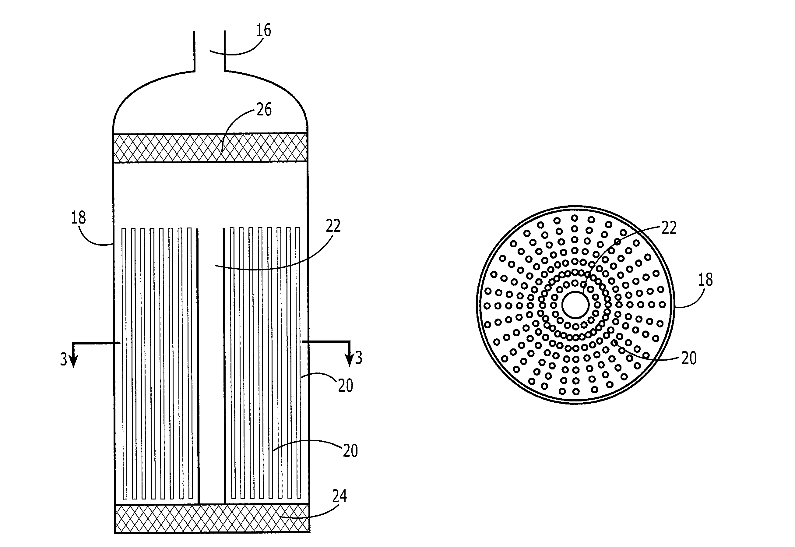
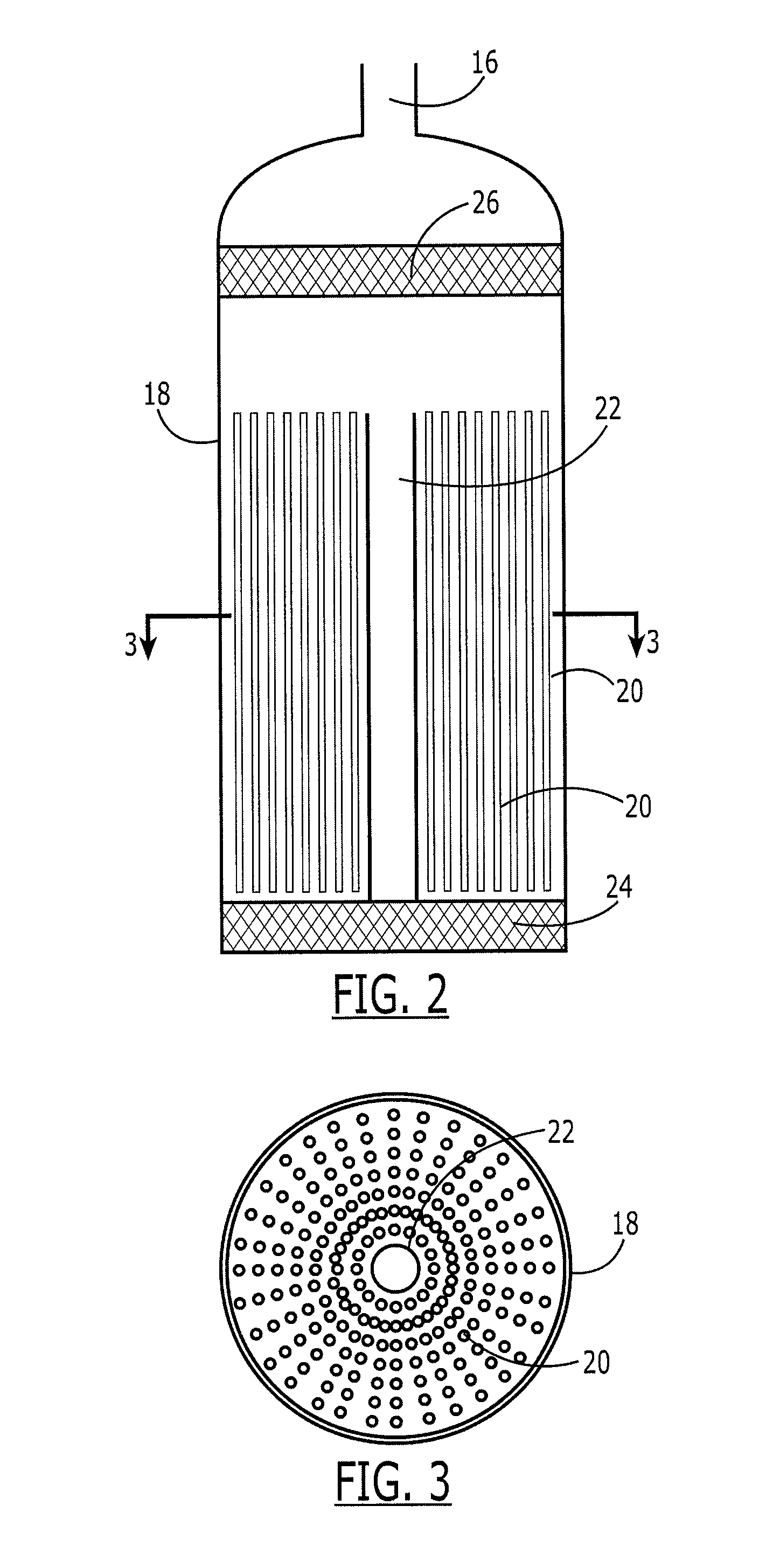
[0006]An apparatus and method for vaporizing liquid are therefore provided which address at least some of the shortcomings of conventional fuel supply systems and which provide still other advantages. In this regard, the method and apparatus for vaporizing liquid employ a plurality of rods disposed within a storage vessel that serve as the heat transfer element. While the plurality of rods are generally submerged by the liquid fuel to facilitate heat transfer and vaporization of the liquid fuel, the rods may be packed closely together such that the liquid inventory required to maintain the rods in a submerged state is substantially less than required by conventional fuel supply systems, thereby permitting the weight of a fuel supply system that incorporates the apparatus and method of one embodiment of the present invention to be reduced while still permitting effective vaporization of the fuel.
[0008]In accordance with another aspect of the present invention, an apparatus for vaporizing liquid is provided that includes the storage vessel, a plurality of rods, such as a plurality of cylindrical rods, and one or more downcomers extending through the plurality of rods and defining a passage to enable liquid to flow therethrough. In accordance with this aspect in the present invention, the plurality of rods and the downcomers are positioned so to be substantially parallel to one another within the storage vessel. In addition to being parallel, the downcomers may extend to a position that is equal with or that extends beyond the plurality of rods to facilitate the flow of liquid therethrough. The apparatus also includes a heater for heating the plurality of rods.
[0011]In accordance with embodiments of the present invention, an apparatus and method are provided for vaporizing liquid in such a way that the plurality of rods that serve as the heat transfer elements may be submerged within a liquid so as to facilitate heat transfer and vaporization of the liquid in such a manner that the quantity of liquid required to submerge the rod is reduced relative to conventional designs. In one embodiment, the plurality of rods are disposed such that the liquid in which the rods are immersed is no more than 10% by volume of the rods. Accordingly, the liquid inventory that is required to submerge the rods and to provide for effective heat transfer is reduced and, in turn, the weight of the fuel supply system is advantageously reduced.

Problems solved by technology

As such, the liquid that is normally required to submerge the balls can create a potentially large fluid inventory which, in turn, adds to the weight of the fuel supply system.

Method used


Image

  • Method and apparatus for vaporizing liquid
  • Method and apparatus for vaporizing liquid
  • Method and apparatus for vaporizing liquid

Examples


Embodiment Construction

[0018]The present inventions now will be described more fully hereinafter with reference to the accompanying drawings, in which some, but not all embodiments of the inventions are shown. Indeed, these inventions may be embodied in many different forms and should not be construed as limited to the embodiments set forth herein; rather, these embodiments are provided so that this disclosure will satisfy applicable legal requirements. Like numbers refer to like elements throughout.

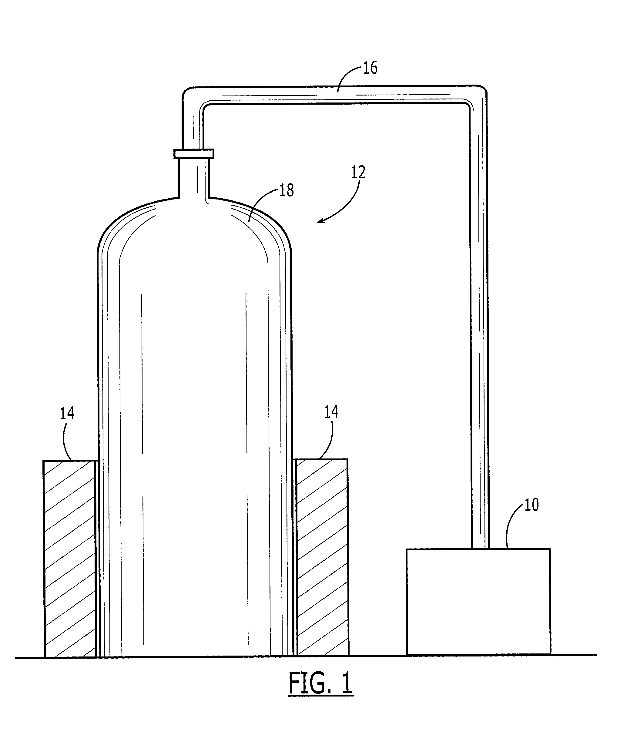
[0019]Referring now to FIG. 1, a chemical laser 10 and an associated fuel supply system 12 are depicted. A chemical laser may be embodied in a variety of different manners, including, for example, as a chemical oxygen-iodine laser. A chemical laser typically requires a supply of gaseous fuel. A fuel supply system can provide a variety of different types of fuel, such as chlorine in one embodiment. In order to reduce the overall weight of the fuel supply system, however, the fuel is generally stored in liquid f...


PUM


Abstract

An apparatus and method for vaporizing liquid are provided which employ a plurality of rods disposed within a storage vessel that serve as the heat transfer element. While the plurality of rods are generally submerged by the liquid fuel to facilitate heat transfer and vaporization of the liquid fuel, the rods may be packed closely together such that the liquid inventory required to maintain the rods in a submerged state is substantially less than required by conventional fuel supply systems, thereby permitting the weight of a fuel supply system that incorporates the apparatus and method to be reduced while still permitting effective vaporization of the fuel.

Description

FIELD OF THE INVENTION[0001]Embodiments of the of the present invention relate generally to an apparatus and method for vaporizing liquid and, more particularly, to an apparatus and method for vaporizing liquid that utilize a plurality of rods as heat transfer elements in order to reduce the liquid inventory required for heat transfer purposes.BACKGROUND OF THE INVENTION[0002]Chemical lasers require a gaseous fuel supply in which the fuel is provided in a vaporized form. It is also generally advisable that the fuel supply system associated with a chemical laser be relatively light. In order to reduce the weight of the fuel supply system, the fuel is therefore generally stored as a liquid. Since the fuel is stored as a liquid, the fuel supply system must be capable of providing the heat required for vaporization of the liquid in real time, that is, as the chemical laser is activated and requires a supply of gaseous fuel. The chemical laser operates for very brief periods, during whic...

Claims


Application Information

Patent Timeline
Patent Type & Authority Patents(United States)
IPC IPC(8): F22B1/02
CPCF22B1/30F22B1/02
Inventor ULLMAN, ALAN Z.TOMASSIAN, ALBERT D.WHERLEY, BRIAN L.NEWMAN, CLYDE D.
Owner THE BOEING CO
Learn More