Fuel injection apparatus for and method of internal combustion engine, and fuel injection valve

a technology of fuel injection apparatus and internal combustion engine, which is applied in the direction of fuel injection apparatus, combustion engine, charge feed system, etc., can solve the problems of large hydrocarbon hc discharge amount from the engine, and the optimization of fuel spray with respect to the change in air movement, so as to achieve efficient vaporization of fuel spray

Inactive Publication Date: 2007-03-15
HITACHI LTD
View PDF27 Cites 3 Cited by
  • Summary
  • Abstract
  • Description
  • Claims
  • Application Information

AI Technical Summary

Benefits of technology

[0011] An object of the present invention is to optimize the fuel spray with respect to a change in the air movement due to providing a rectifying plate, to thereby efficiently vaporize the fuel spray.
[0013] In the case where the rectifying plate partitions the inlet pipe into upper and lower, a flow velocity at a center of a flow path on a upper side, and at a center of a flow path on a lower side is increased. Consequently, a flow velocity distribution of air in a cylinder diameter direction of a valve head of an inlet valve becomes a peak value on both sides of the valve head center. Therefore, by directly discharging most of the fuel onto both sides of the center of the valve head, vaporization of the fuel spray can be performed with good efficiency.

Problems solved by technology

Therefore, at the time of starting, a large amount of fuel flows into the combustion chamber in the liquid state, so that the discharge amount of hydrocarbons HC from the engine becomes great.
However up to now, the fuel spray with respect to the change in the air movement has not been optimized.

Method used


Image

  • Fuel injection apparatus for and method of internal combustion engine, and fuel injection valve
  • Fuel injection apparatus for and method of internal combustion engine, and fuel injection valve
  • Fuel injection apparatus for and method of internal combustion engine, and fuel injection valve

Examples


first embodiment

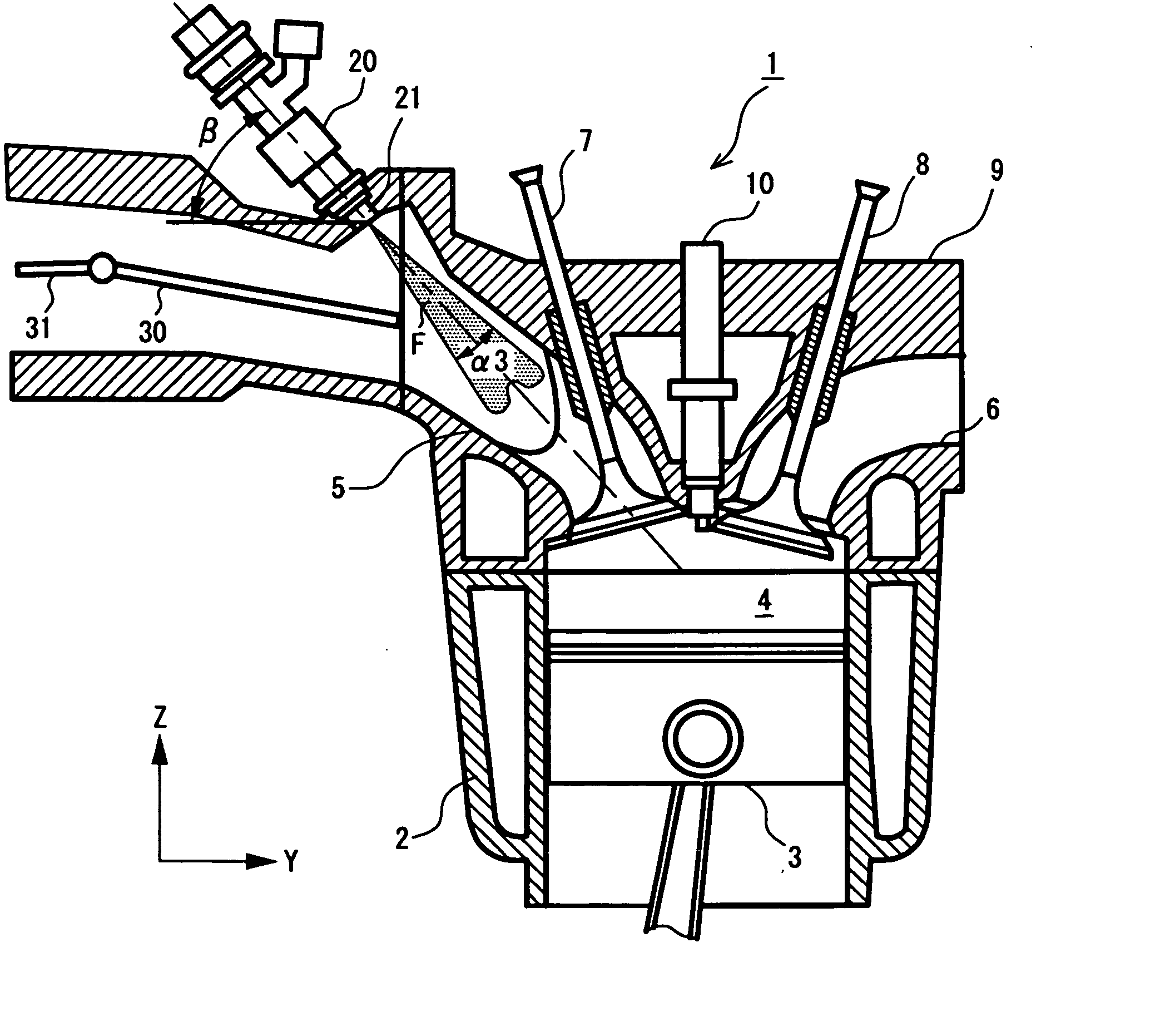
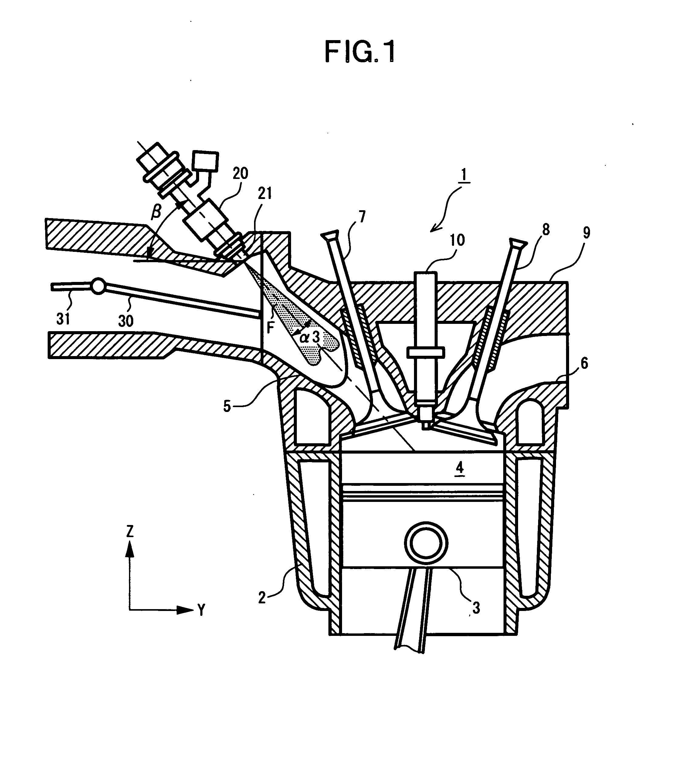
[0034]FIG. 1 shows a longitudinal section of an internal combustion engine, and FIG. 2 schematically shows a top cross-section of the internal combustion engine.

[0035] Engine 1 includes; a cylinder block 2, a cylinder head 9, and a piston 3 which is inserted into cylinder block 2, and a combustion chamber 4 is formed by cylinder head 9 and piston 3.

[0036] An inlet pipe 5 and an exhaust pipe 6 formed in cylinder head 9 open into combustion chamber 4, and two inlet valves 7A and 7B, and two exhaust valves 8A and 8B are arranged in cylinder head 9.

[0037] A fuel injection valve 20 is arranged on the upstream side of inlet pipe 5. Fuel injection valve 20 is arranged at a position where it can spray fuel towards the inlet valves 7A and 7B. A spark plug 10 is provided on the central upper portion of combustion chamber 4.

[0038] A rectifying plate 30 is provided inside inlet pipe 5, and a tumble control valve 31 is provided on the upstream side of rectifying plate 30.

[0039] Rectifying p...

second embodiment

[0081]FIGS. 8 and 9 show a nozzle section 21 of a fuel injection valve 20 of a second embodiment. FIG. 8 is a longitudinal section of the nozzle section 21, and FIG. 9 is a view of nozzle section 21 seen from the tip end side.

[0082] Internal combustion engine which uses fuel injection valve 20 shown in FIG. 8 and FIG. 9, is similar to the first embodiment.

[0083] In the tip end of nozzle section 21 of fuel injection valve 20, a nozzle plate 13 is secured to a holder 15 by means of a guide 14.

[0084] In nozzle plate 13, a plurality of injection nozzles 16 are bored.

[0085] Inside holder 15 is provided a ball valve 17 capable of moving up and down, and by raising ball valve 17, a small gap between guide 14 and ball valve 17 allows fuel to flow, so that fuel is injected from injection nozzles 16.

[0086] Injection nozzles 16 are pierced at an incline with respect to the central axis of fuel injection valve 20, and an X-axis, a Y-axis, and a Z-axis, and a first region to a fourth region...

third embodiment

[0120]FIG. 14 is a cross-sectional view of an internal combustion engine, and FIG. 15 is a plan view of FIG. 14.

[0121] As shown in FIGS. 14 and 15, in an internal combustion engine 51, a piston 54 is inserted into a cylinder 53 formed in a cylinder block 52, so as to be capable of reciprocating in cylinder 53.

[0122] A cylinder head 55 is fitted to the top of cylinder 53, and a combustion chamber 61 is formed by the head of the piston 54, and cylinder head 55.

[0123] A spark plug 62 is provided at a central portion of cylinder head 55. Furthermore, two inlet valves 56a and 56b, and two exhaust valves 57a and 57b are arranged in the cylinder head 55 with the spark plug 62 at the center.

[0124] An inlet port 58 which is connected to valve seats of two inlet valves 56a and 56b is formed in cylinder head 55. Inlet port 58 extends from diagonally above cylinder 53 to the cylinder head 55, and is branched into two along the way, and connected to the valve seats of respective inlet valves...


PUM


Abstract

Fuel injection technology of an internal combustion engine is configured in such a manner that in a case where in inlet pipe interior of the engine is partitioned by a rectifying plate into upper and lower flow paths, a flow velocity at a center of the flow path on an upper side, and at a center of the flow path on a lower side is increased. Consequently, a flow velocity distribution of air in a cylinder diametrical direction of a valve head of an inlet valve becomes a peak value on both sides of the valve head center. Therefore, by impinging most of the injected fuel spray upon both sides of the center of the valve head, vaporization of the fuel spray can be performed with good efficiency.

Description

BACKGROUND OF THE INVENTION [0001] 1. Field of the Invention [0002] The present invention relates to a fuel injection apparatus for an internal combustion engine, which injects fuel from an upstream side of an inlet valve towards the inlet valve, and to a fuel injection method of an internal combustion engine, and a fuel injection valve. [0003] 2. Description of the Related Art [0004] In Japanese Unexamined Patent Publication No. 2001-295738, there is disclosed a fuel injection apparatus for an internal combustion engine in which an extension pipe is provided on a tip end portion of a fuel injection valve, and fuel is injected towards the inlet valve via this extension pipe. [0005] Furthermore, in Japanese Unexamined Patent Publication No. 2004-225598 there is disclosed a fuel injection valve where, in a engine furnished with two inlet valves in respective cylinders, a flow amount of fuel injected from a fuel injection valve is a maximum value at a position displaced from a central ...

Claims


Application Information

Patent Timeline
Patent Type & Authority Applications(United States)
IPC IPC(8): F02B31/00F02M61/14
CPCF02B31/085F02B2275/16F02B2275/48Y02T10/123F02M61/1853Y02T10/125Y02T10/146F02M61/145Y02T10/12
Inventor ODA, TOMOAKIFURUDATE, HITOSHIFURUYA, JUNICHISUKEGAWA, YOSHIHIRO
Owner HITACHI LTD
Why Eureka
Try Eureka