
Driving circuit of stepping motor
A stepping motor and drive circuit technology, applied in the direction of motor generator control, electrical components, control systems, etc., can solve the problem of low torque
Patent Information
- Authority / Receiving Office
- CN · China
- Current Assignee / Owner
- Publication Date
- 2011-06-22
Smart Images
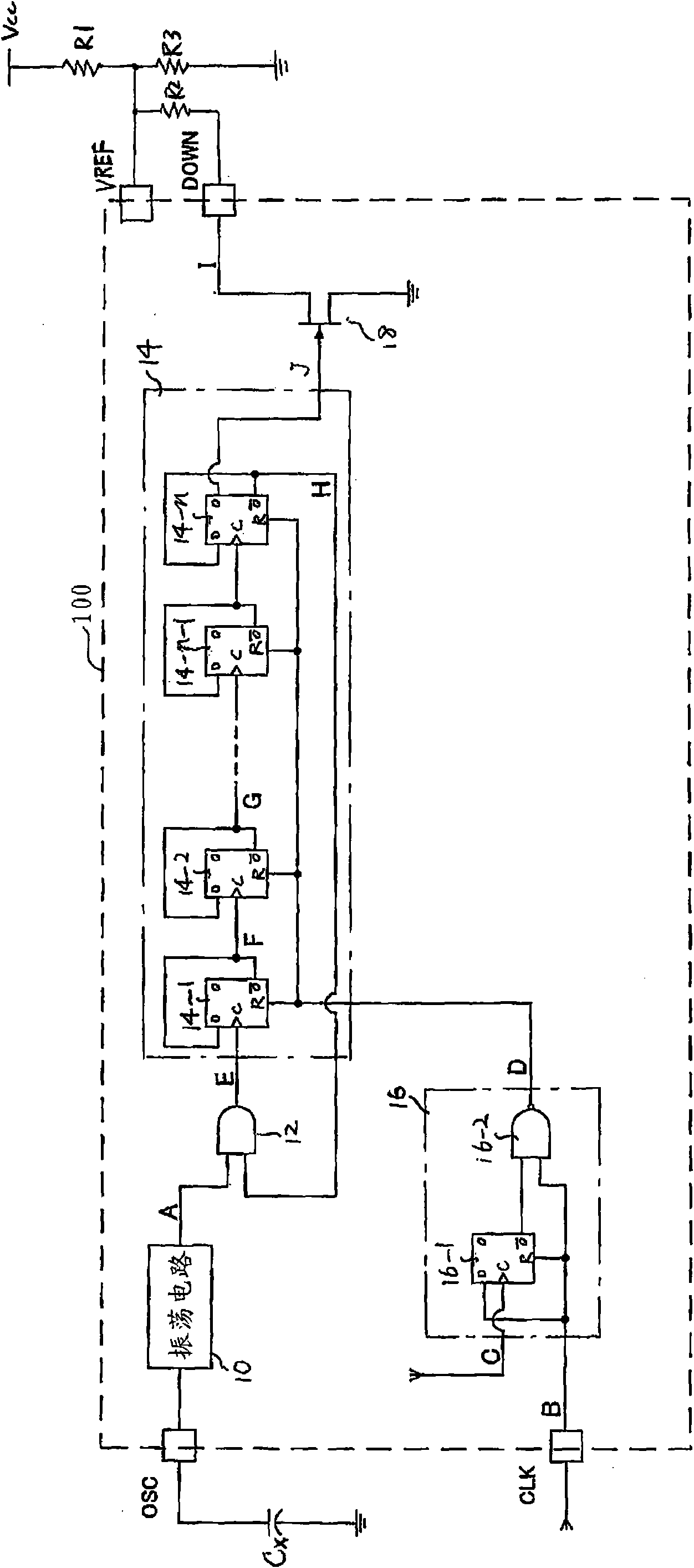
Figure 1 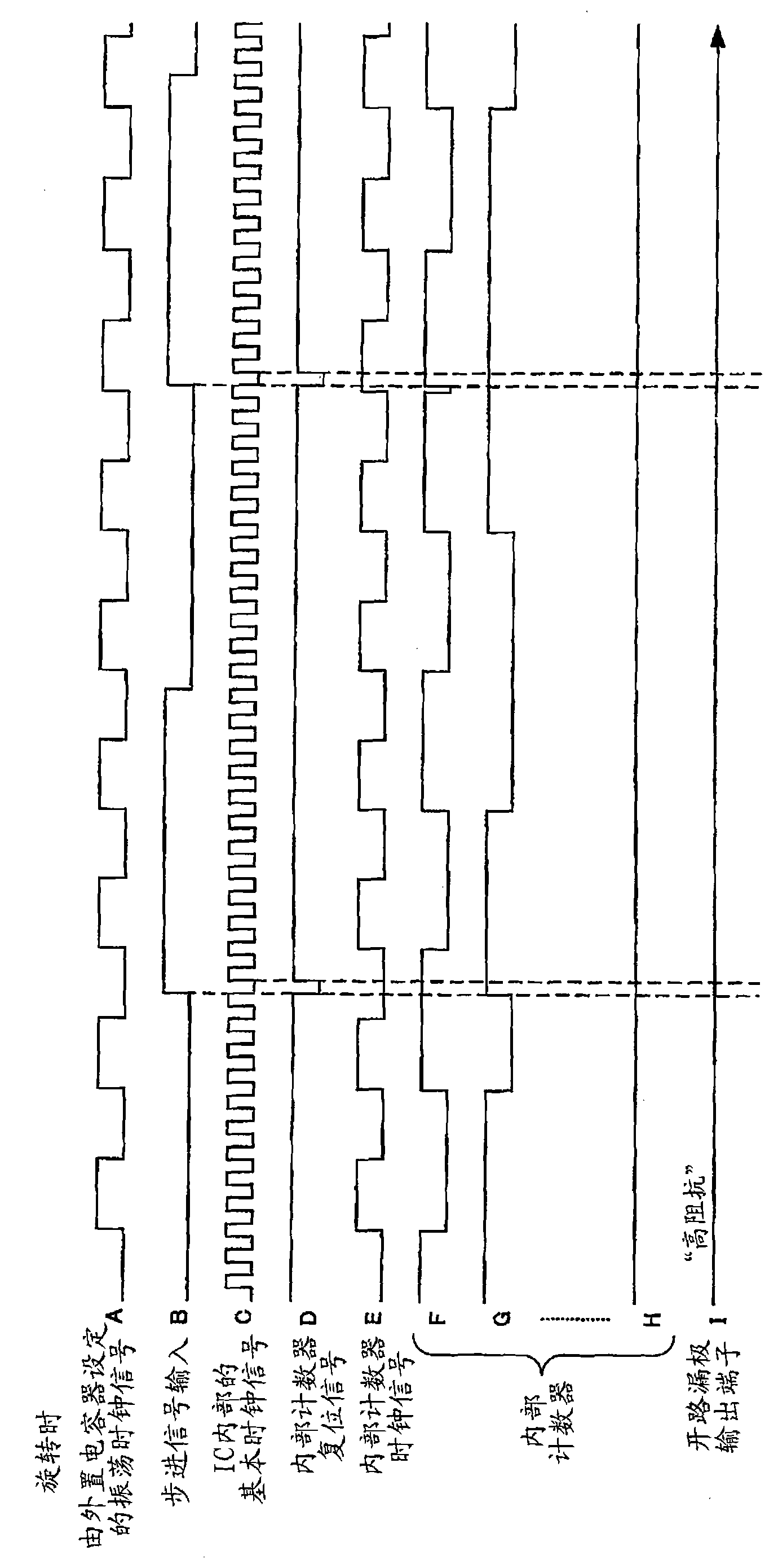
Figure 2 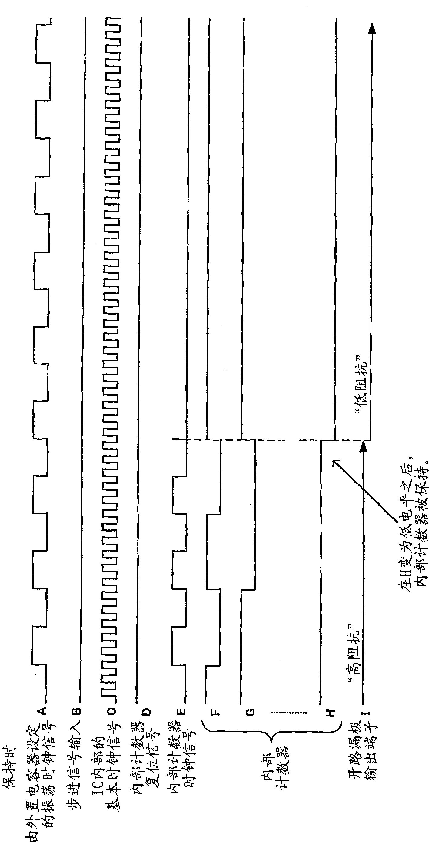
Figure 3
Abstract
Description
technical field
[0001] The invention relates to a driving circuit of a stepping motor. Background technique
[0002] In order to rotationally drive a stepping motor, it is necessary to provide torque. In particular, it is necessary to provide high torque at the initial stage of rotation, but it is also possible to make the torque low in the rotation holding state of continuous rotation. Therefore, there is an advantage in that power consumption can be reduced by performing control to reduce the energizing current flowing to the stepping motor in the rotation holding state. In order to switch the energized current, it is necessary to switch the current setting reference voltage of the drive circuit of the stepping motor.
[0003] Figure 5 The configuration of a conventional stepping motor drive circuit is shown. In the initial stage of rotation, switch S1 is turned off to set the reference voltage VREF for current setting to be higher. In the rotation holding state, switc...
Examples
Embodiment Construction
[0019] Such as figure 1 As shown, the stepping motor drive circuit 100 according to the embodiment of the present invention is configured to include an oscillation circuit 10 , an AND element 12 , a shift register 14 , a reset circuit 16 and a switching element 18 . It is preferable that the driving circuit 100 is formed in one semiconductor chip together with the basic driving circuit of the stepping motor.
[0020] The oscillation circuit 10 oscillates at a frequency corresponding to the capacitance value of a capacitor Cx connected to an external terminal OSC, and outputs an oscillation clock signal A. The oscillating clock signal A is input to the AND element 12 .
[0021] The "AND" element 12 receives the oscillating clock signal A and the inverted output Q of the flip-flop 14-n of the last stage of the shift register 14, and the flip-flop 14-n of the last stage of the oscillating clock signal A and the shift register 14 When the inverted output Q of n is high level, t...