
Radiographic inspection compensation method
A technology of radiography and compensation method, which is applied in the direction of using radiation for material analysis, using wave/particle radiation for material analysis, and measuring devices, etc., which can solve the problems of relatively high environmental requirements on the detection site, low production efficiency, and high equipment costs. To achieve the effect of ensuring image quality and sensitivity, low equipment cost, and low production cost
Patent Information
- Authority / Receiving Office
- CN · China
- Patent Type
- Applications(China)
- Current Assignee / Owner
- Publication Date
- 2005-04-13
- Estimated Expiration
- Not applicable · inactive patent
Smart Images
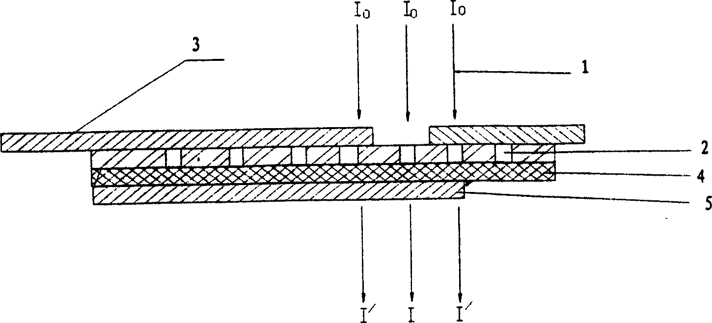
Figure 1 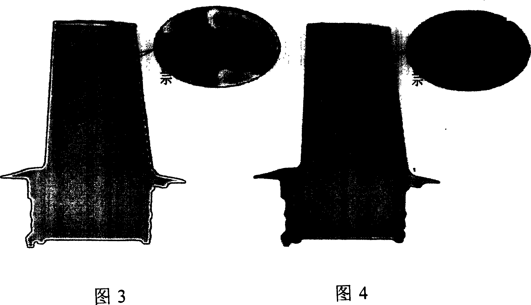
Figure 2 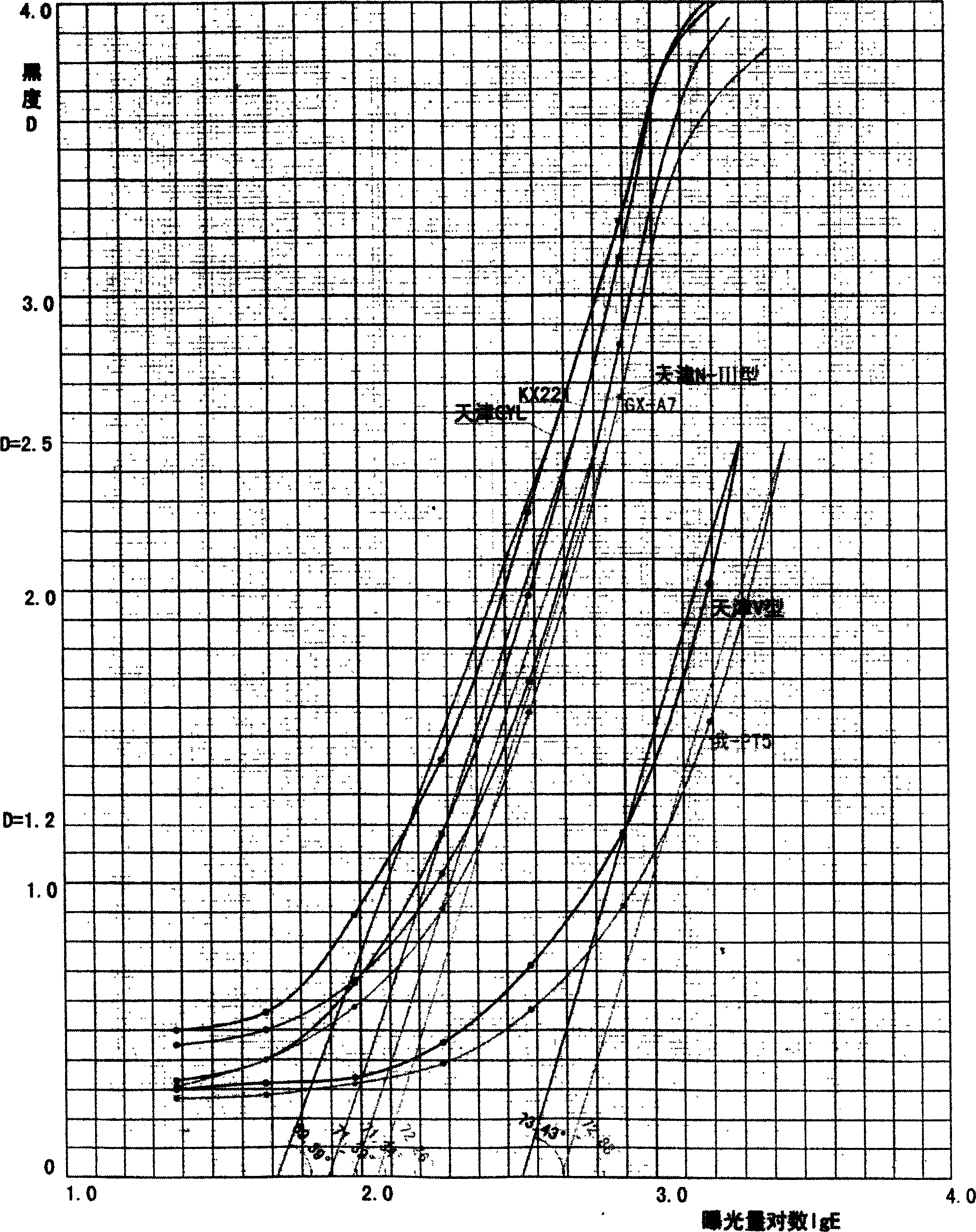
Figure 3
Abstract
Description
technical field
[0001] The invention relates to a non-destructive testing of equipment components, in particular to a radiographic inspection and compensation method. Background technique
[0002] As we all know, it is a necessary procedure to strictly test the quality of processed or modified equipment parts in industrial production, and there are many inspection methods. However, more stringent quality inspection is required for the inspection of some equipment components with high performance requirements, complex structure, and inner cavity. For example, the high-pressure turbine blade is a key part of the aviation gas turbine engine. There are complex cavities inside the blade to ensure the cooling and strength of the blade, and a large number of tiny exhaust ports are prepared on the surface of the blade. The change of the inner cavity of the blade reflects the degree of cooling of the blade, and reflects the extent to which the operating temperature of the blade exce...
Examples
Embodiment Construction
[0019] The selected aero-engine turbine blade is a cast grid cavity structure, the purpose is to check the cleanliness of the inner cavity to prevent foreign matter from blocking the airflow channel and ensure the cooling effect of the blade. First, use the comparative measurement method to analyze and select the film characteristics; take an X-ray film of length × width (11 inches × 1.5 inches) and wrap it with black paper, and cover it with a lead plate. The thickness must be sufficient to prevent the film from being affected by X-rays. There are holes with a diameter of 15 mm on the lead plate. During exposure, the lead plate is gradually moved, and the X-rays pass through the small holes to expose the film in sections, such as figure 1 shown. In this example, SEIFERT ISOVOT320 / 13 fixed X-ray machine is selected, the basic transillumination parameters are tube voltage 95KV, tube current 3mA, focal length 1800mm, and each exposure time is 8, 16, 32, 94, 128, 256, 512 second...