
Power supply apparatus for ion accelerator
Patent Information
- Authority / Receiving Office
- US · United States
- Current Assignee / Owner
- Publication Date
- 2007-06-28
Smart Images
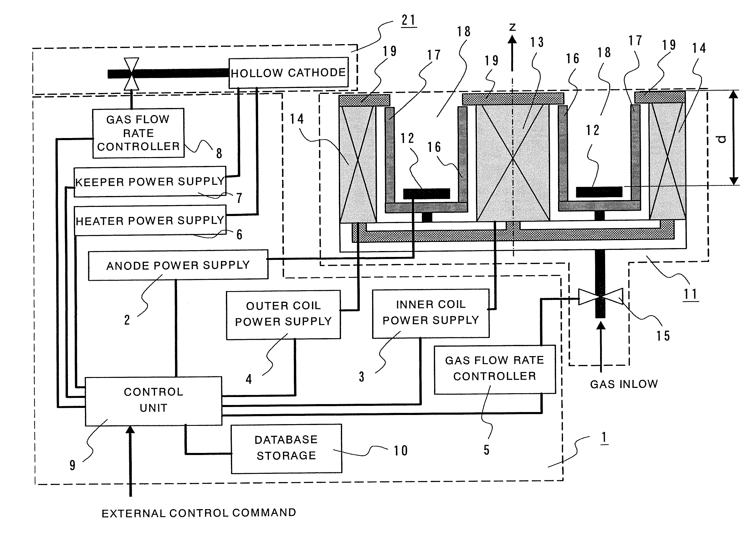
Figure 1 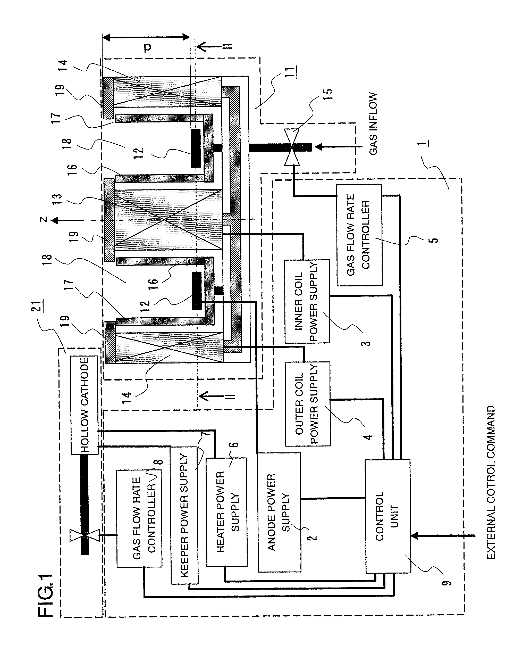
Figure 2 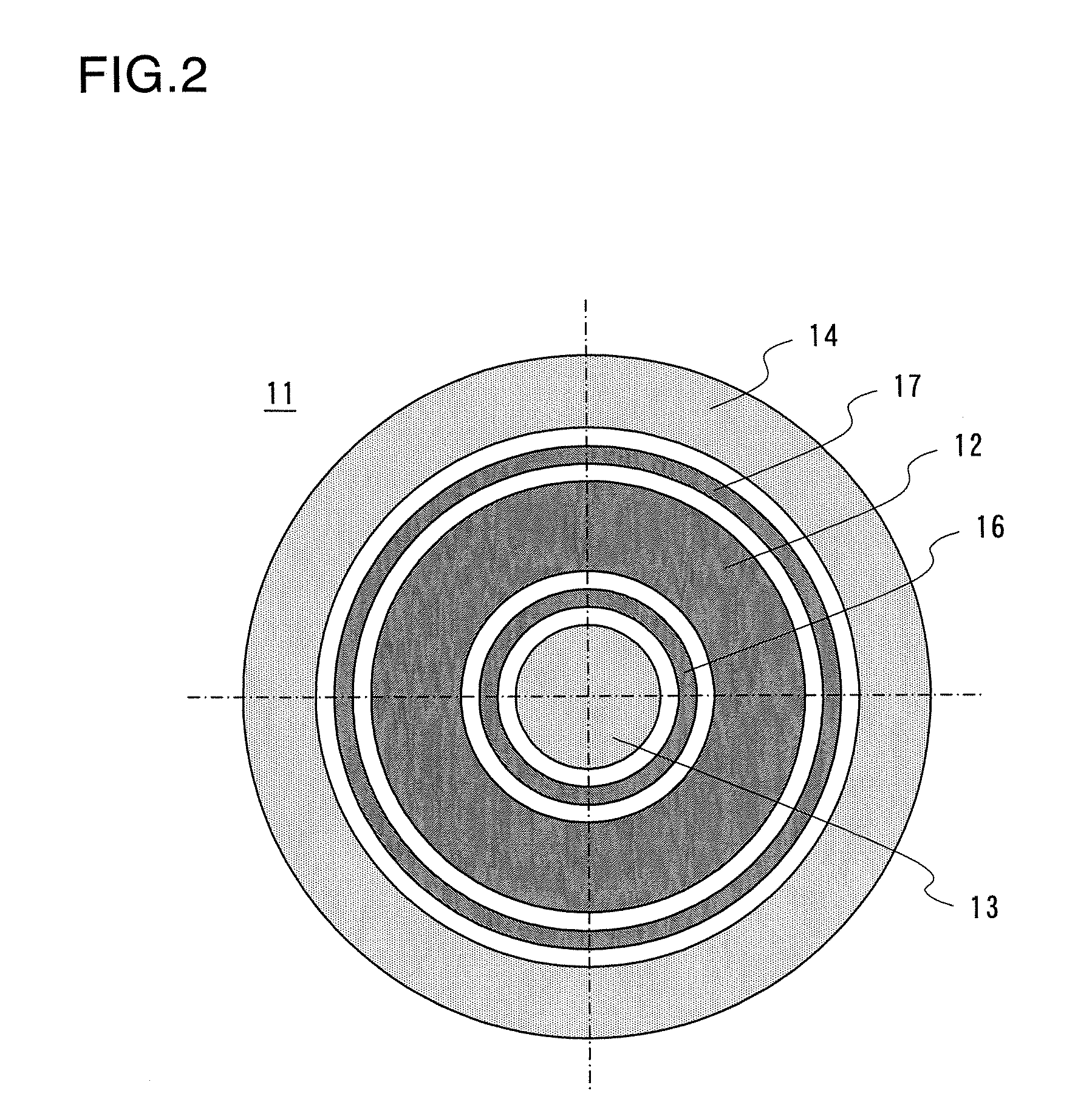
Figure 3
Abstract
Description
BACKGROUND OF THE INVENTION
[0001] 1. Field of the Invention
[0002] The present invention relates to a power supply apparatus for an ion accelerator which is an electric discharge device for accelerating ions. More particularly, the invention pertains to a power supply apparatus for a Hall thruster which is an electric propulsion device mounted on an artificial satellite, for example.
[0003] 2. Description of the Background Art
[0004] A Hall thruster introduces gas from one end of an annular discharge channel, ionizes and accelerates the gas therein, and ejects the ionized gas through the other end of the discharge channel. The Hall thruster produces a thrust due to reaction of an outgoing flow of ions from the discharge channel. A radial magnetic field is formed in the annular discharge channel. The Hall effect produced by the radial magnetic field causes an azimuthal drift of electrons within the annular discharge channel so that the electrons are kept from moving in an axial dire...
Examples
first embodiment
[0020]FIG. 1 is a configuration diagram of a power supply apparatus 1 according to a first embodiment of the present invention. Referring to FIG. 1, the power supply apparatus 1 controls a Hall thruster 11 which is an ion accelerator as well as a hollow cathode device 21 for supplying electrons to the Hall thruster 11. FIG. 1 contains a cross-sectional diagram of the Hall thruster 11 taken by a plane containing a central axis of the Hall thruster 11 which is a device having an annular configuration. The Hall thruster 11 includes an anode 12, an inner coil 13 and an outer coil 14 for forming a radial magnetic field, a gas flow rate regulator 15, as well as an inner ring 16 and an outer ring 17 which together form a ring-shaped ion acceleration zone 18. FIG. 2 is a cross-sectional diagram of the Hall thruster 11 taken along lines II-II of FIG. 1 (or taken by a plane perpendicular to the central axis of the Hall thruster 11). The anode 12, the inner ring 16 and the outer ring 17 are co...
second embodiment
[0053] While the control unit 9 controls the Hall thruster 11 such that the coil current Ic becomes approximately proportional to the root of the anode voltage Va in the foregoing first embodiment, the control unit 9 controls the Hall thruster 11 such that the coil current Ic becomes approximately proportional to the anode voltage Va in a second embodiment of the invention. Generally, the electron velocity within the Hall thruster 11 is determined by classical diffusion in a region of low magnetic flux density and by anomalous diffusion (Bohm diffusion) in a region of high magnetic flux density. When the anomalous diffusion is dominant, the electron mobility and electron velocity can be expressed by equations (8) and (9) below, respectively: μa=116B(8)Ve_a≅μaE∝(β×Va) / (d×B)∝VaIc(9)
[0054] As compared to equation (6), equation (9) contains (β×Va) / (d×B) and Va / Ic, either of which may be used as a parameter on which the discharge oscillation is dependent. Even when the experimental re...
third embodiment
[0056] It is possible to operate the Hall thruster 11 in a stable state in which the discharge oscillation is unlikely to occur by controlling the Hall thruster 11 in the manner described earlier with reference to the first embodiment. Specifically, the Hall thruster 11 can be operated in a stable fashion in every operating range if appropriate values of the coil current Ic are selected in accordance with any given values of the anode voltage Va and the gas flow rate Q. It is not only important to operate the Hall thruster 11 in this way when the Hall thruster 11 is under steady-state operating conditions; it is also extremely effective to operate the Hall thruster 11 in aforementioned way for making the discharge oscillation less likely to occur to achieve improved operational stability of the Hall thruster 11 especially when the anode voltage Va rises during thruster startup or when the Hall thruster 11 is under transient conditions where the anode voltage Va and the gas flow rate...