
Control method of radio communication system, radio communication system, and radio communication apparatus
a control method and radio communication technology, applied in the direction of electrical equipment, radio transmission, transmission path sub-channel allocation, etc., can solve the problems of increased frequency, difficult transmission, and changing environment, and achieve fast and reliable effects
Patent Information
- Authority / Receiving Office
- US · United States
- Patent Type
- Applications(United States)
- Current Assignee / Owner
- Publication Date
- 2012-08-30
Smart Images
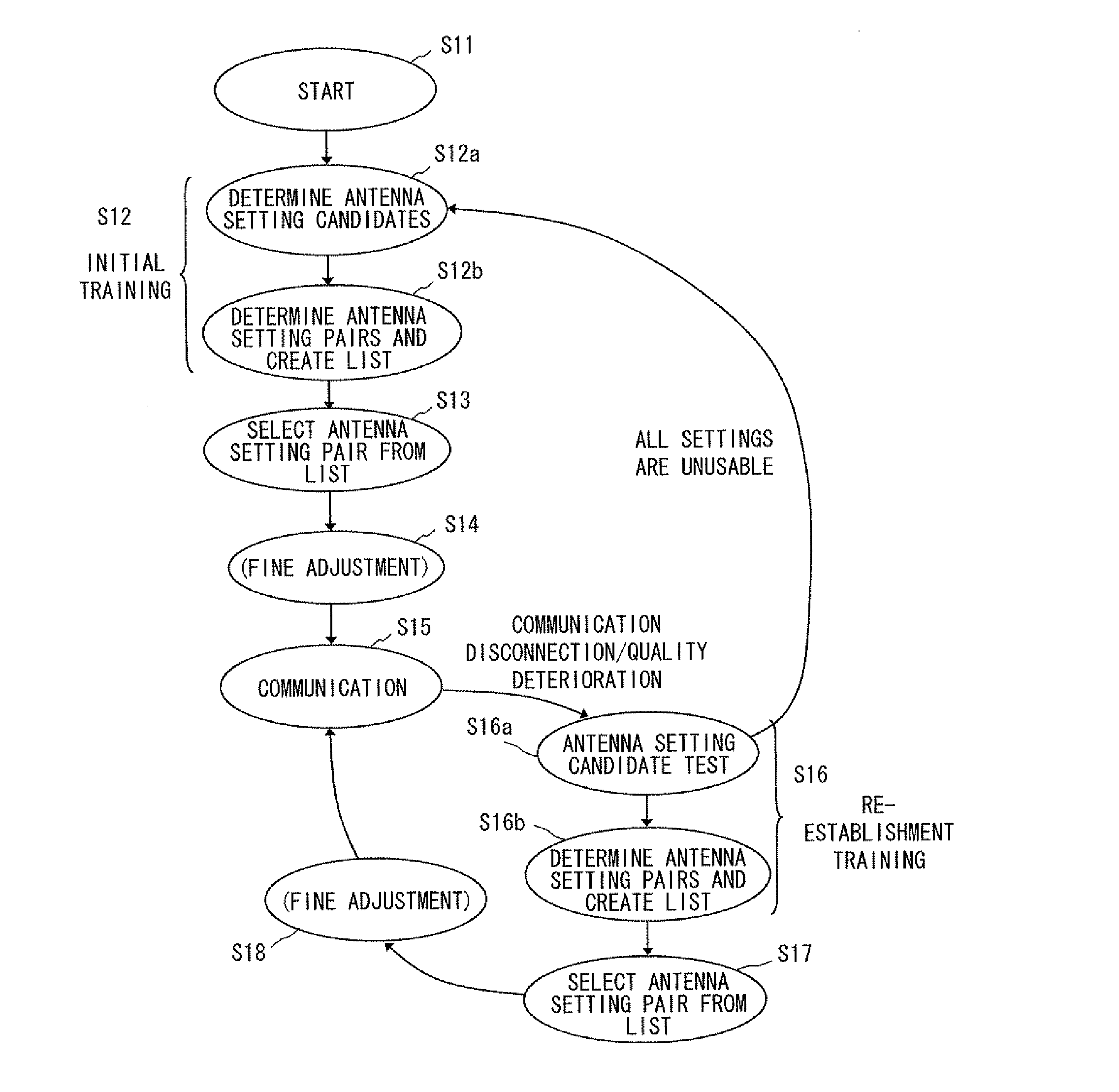
Figure 1 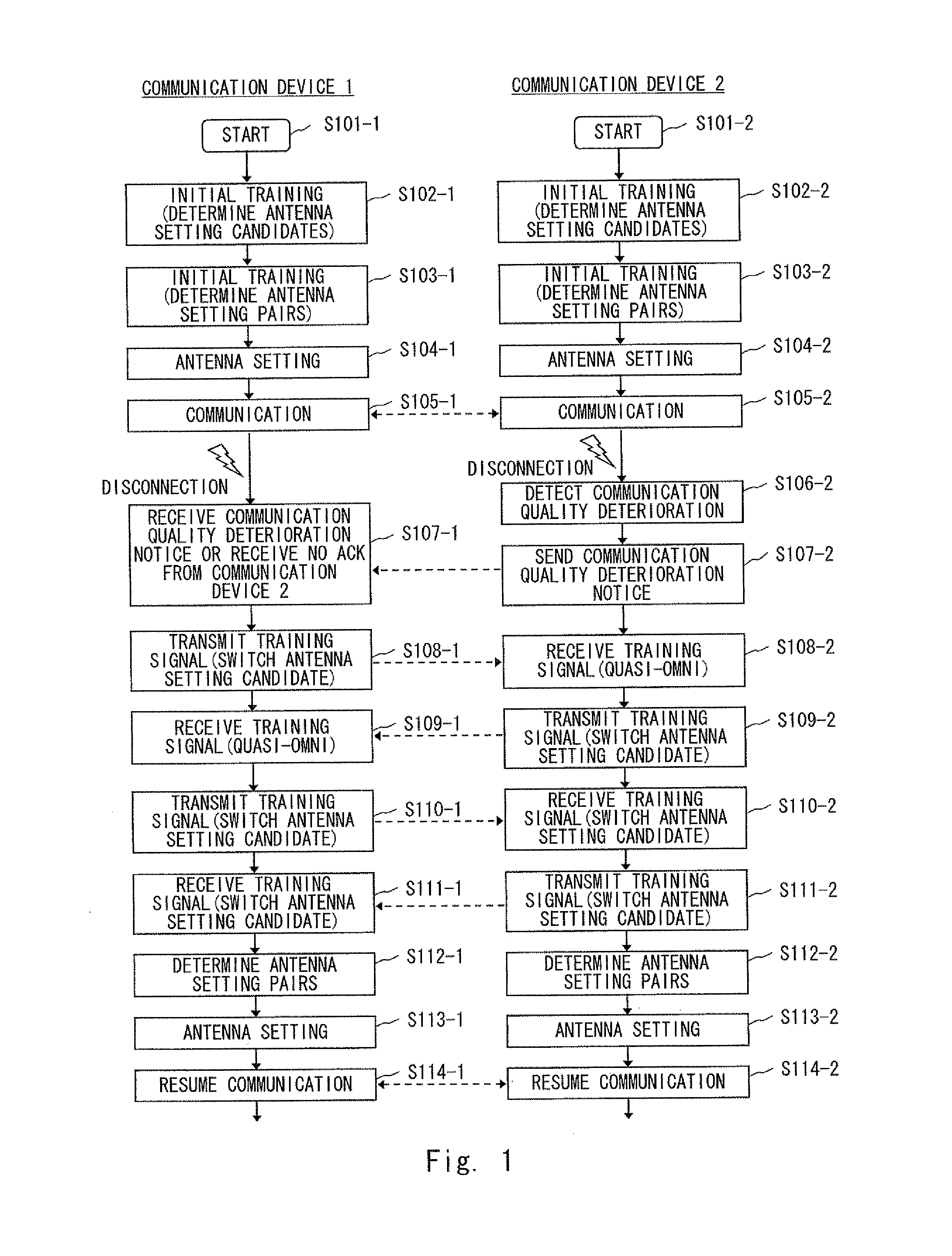
Figure 2 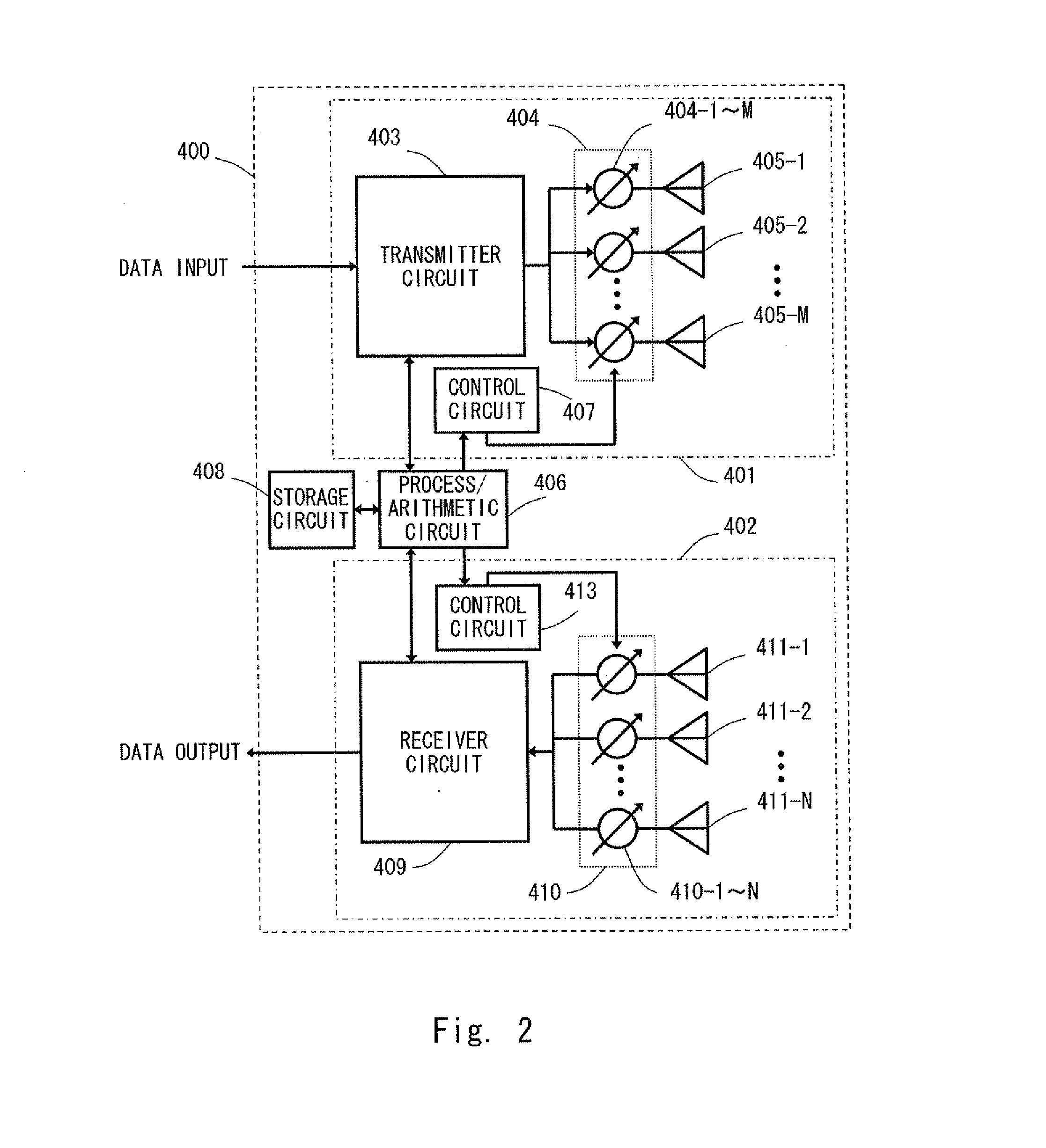
Figure 3
Abstract
Description
TECHNICAL FIELD
[0001] The present invention relates to a system that performs radio communication by adaptively controlling radio beams, and its control method. In particular, the present invention relates to a method for re-establishing a link (method for resuming communication) when communication is disconnected or communication quality is deteriorated due to a shielding obstacle or the like.BACKGROUND ART
[0002] In recent years, use of radio devices using wideband millimeter waves (30 GHz to 300 GHz) has become increasingly widespread. The millimeter-wave radio technology has been expected to be used especially for high-rate radio data communication in the order of gigabit such as radio transmission of high-resolution images (for example, see Non-patent literatures 1, 2 and 3).
[0003] However, millimeter waves having high frequencies have a high rectilinear propagation property, and therefore they cause a problem in cases where radio transmission is to be implemented indoors. In addit...
Examples
first exemplary embodiment
[0072]A radio communication system according to this exemplary embodiment includes transceivers 400 and 500 having a directivity-controllable antenna for beam forming. There is no particular restriction on the directivity control mechanism of the directivity-controllable antenna of the transceivers 400 and 500. For example, the directivity-controllable antenna of the transceivers 400 and 500 may be a phased array antenna, a sector-selectable antenna, or a mechanically-movable antenna.
[0073]FIG. 2 shows an example of a configuration of the transceiver 400 having a phased array antenna as the directivity-controllable antenna (circuits inessential to the explanation of the operation are omitted). One antenna array includes M transmission radiating elements, and another antenna array includes N reception radiating elements. A transmitter 401 includes a transmitter circuit 403 receiving external data. The output of the transmitter circuit 403 is branched into M outputs and they are input...
second exemplary embodiment
[0118]A second exemplary embodiment according to the present invention is explained with reference to a transition diagram shown in FIG. 6. Note that the configuration of a radio communication system according to this exemplary embodiment may be similar to that of the first exemplary embodiment shown in FIG. 3. Each of states S11 to S18 and transition conditions therebetween in FIG. 6 are similar to the states assigned with the same signs and their transition conditions shown in FIG. 5 described above with the first exemplary embodiment. Therefore, detailed explanation of the states S11 to S18 is omitted.
[0119]In the first exemplary embodiment, the same process is carried out for both when the communication is disconnected and when the communication quality is deteriorated. However, the training for re-establishing the link (S16) described above in the first exemplary embodiment is especially effective when the communication is disconnected and the time synchronization between the c...
third exemplary embodiment
[0122]A third exemplary embodiment according to the present invention is explained with reference to a sequence diagram shown in FIG. 8. The steps shown in this sequence diagram are inserted between the end of FIG. 7A and the top of FIG. 7B. That is, the procedure may be carried out in the order of FIG. 7A, FIG. 8 and FIG. 7B.
[0123]An operation performed in steps S716 to s719 in FIG. 8 is explained. Firstly, the communication device 1 sets the transmitting-antenna setting with values for generating a quasi-omni pattern (S716-1) and sends out training signal (S718-1). The communication device 2 repeatedly receives the training signal (S718-2) while changing the receiving-antenna setting (S717-2) until signal receptions in all or some of the antenna settings detected and determined in the step S702 have been completed (S719-2).
[0124]Processes in steps S720 to S723 are similar to those in the above-described steps S716 to S719 except that the roles of the communication device 1 and 2 a...