
Two-section type waste incinerator
Patent Information
- Authority / Receiving Office
- US · United States
- Current Assignee / Owner
- Publication Date
- 2013-07-25
- Estimated Expiration
- Not applicable · inactive patent
Smart Images
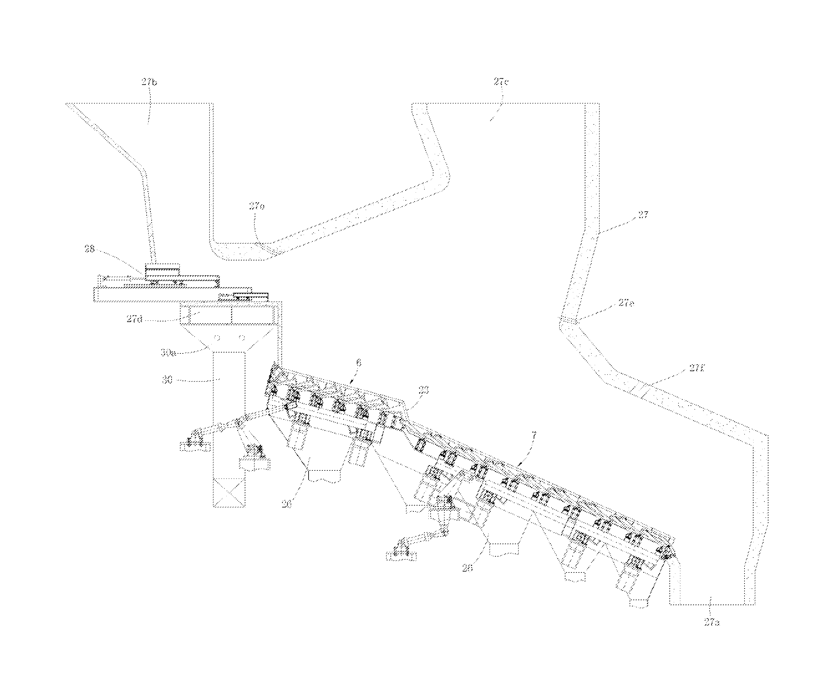
Figure 1 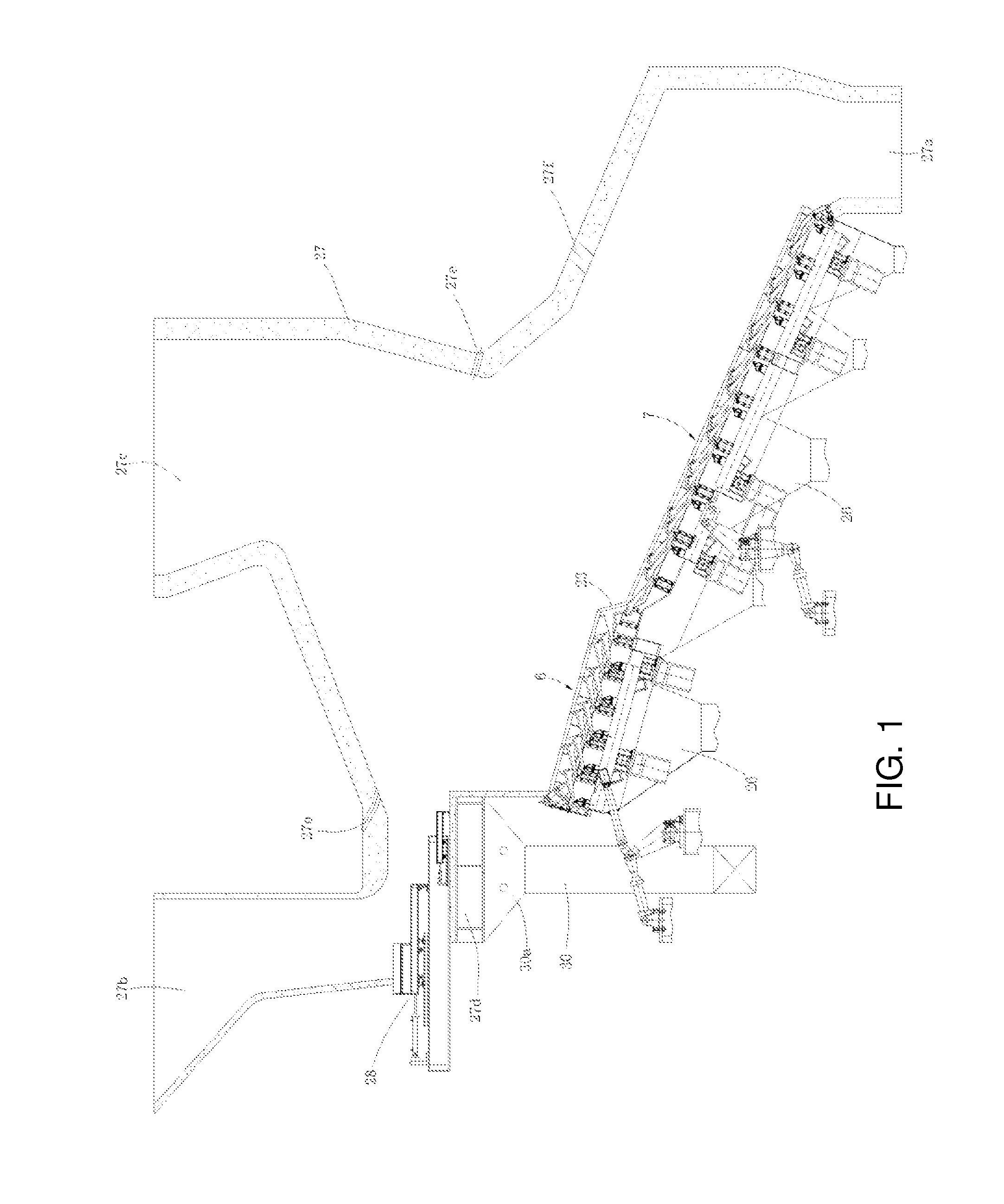
Figure 2 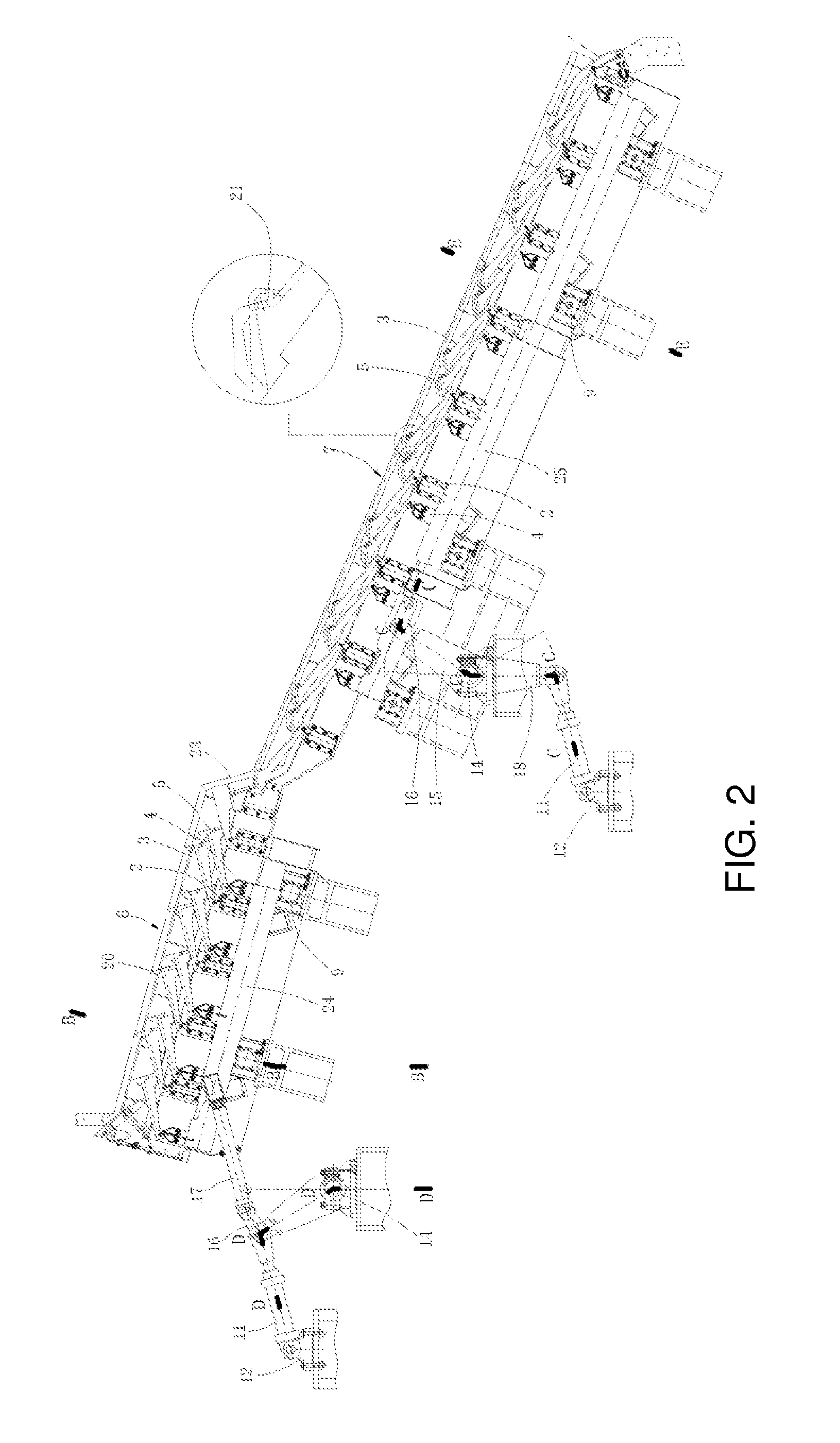
Figure 3
Abstract
Description
FIELD OF THE INVENTION
[0001] The present invention belongs to a field of solid waste incineration processing technology, in particular relates to a municipal solid waste incinerator or namely a municipal household waste incinerator.BACKGROUND OF THE INVENTION
[0002] The existing waste processing technologies mainly include incineration, sanitary landfill, compost, waste recycling, etc. In these common waste processing technologies, the incineration process has the advantages of reducing the gross of the waste remarkably, being harmless thoroughly, occupying small land, utilizing waste heat and minimizing secondary pollution, etc., which comply with the strategy of sustainable development of our country.
[0003] In the existing incineration processes and devices, there are various forms of grate-typed incinerators, the application of which occupies more than 80% of the total amount of waste incineration market all over the world. In one type of incinerator, all grates in the incinerator bo...
Examples
first embodiment
The First Embodiment
[0062]As shown in FIG. 1, a slag removing port 27a is provided at a tail portion of a bottom end of an incinerator body 27, a material feeding bunker 27b is provided at a front portion of a top end of the incinerator body 27 and a smoke outlet 27c is provided at a rear portion of the top end of the incinerator body 27. A smoke passing hole adjacent to the smoke outlet is provided on the upper portion of a rear wall of the incinerator body 27, and an inner cavity of the incinerator body 27 is communicated with a smoke detection means provided outside of the incinerator body through the smoke passing hole. Secondary air supplying holes 27e are provided on a front arch and a back arch of an incinerator body 27, a secondary air supplying device provided outside of the incinerator body is communicated with the inner cavity of the incinerator body 27 through the secondary air supplying holes 27e, and an ignition combustion-supporting hole 27f is provided on the back ar...
second embodiment
The Second Embodiment
[0074]As shown in FIG. 12, in the embodiment, the lever frame of the pusher type section 6 is driven by a front swing arm driving mechanism, the lever frame of the reverse pusher type section is driven by a front straight driving mechanism. The front straight driving mechanism comprises a driving cylinder 11, a driving cylinder seat 12 and a straight driving linkage 19, wherein the cylinder body of the driving cylinder 11 is hinged to the driving cylinder seat 12, a piston rod of the driving cylinder 11 is hinged to one end of the straight driving linkage 19, the other end of the straight driving linkage 19 is connected to the corresponding lever frame. Other structures of the embodiment are the same as the first embodiment, and thus are unnecessary to be described in details here.
third embodiment
The Third Embodiment
[0075]As shown in FIG. 13, in the embodiment, each of a front portion and a rear portion of the reverse pusher type section 7 is provided with a set of reverse pusher levers 25, each set of reverse pusher levers 25 and the corresponding movable beam 4 form a lever frame, each of the front and rear lever frames is equipped with a lateral swing arm driving mechanism. Other structures of the embodiment are the same as the first embodiment, and thus are unnecessary to be described in details here.