
Electrode boiler with electrodes unit
a technology of electrodes and boilers, applied in the field of heat engineering and power engineering, can solve the problems of reducing the overall efficiency of the electrode system at a rather high rate, reducing the fabricability of the device, the electrodes, and the impediment to the intended function of the boiler, etc., to improve the design reliability, improve the service life of the device, and improve the overall efficiency of the electrode system. , the effect of improving the service li
Patent Information
- Authority / Receiving Office
- US · United States
- Patent Type
- Patents(United States)
- Current Assignee / Owner
- Publication Date
- 2017-12-12
Smart Images
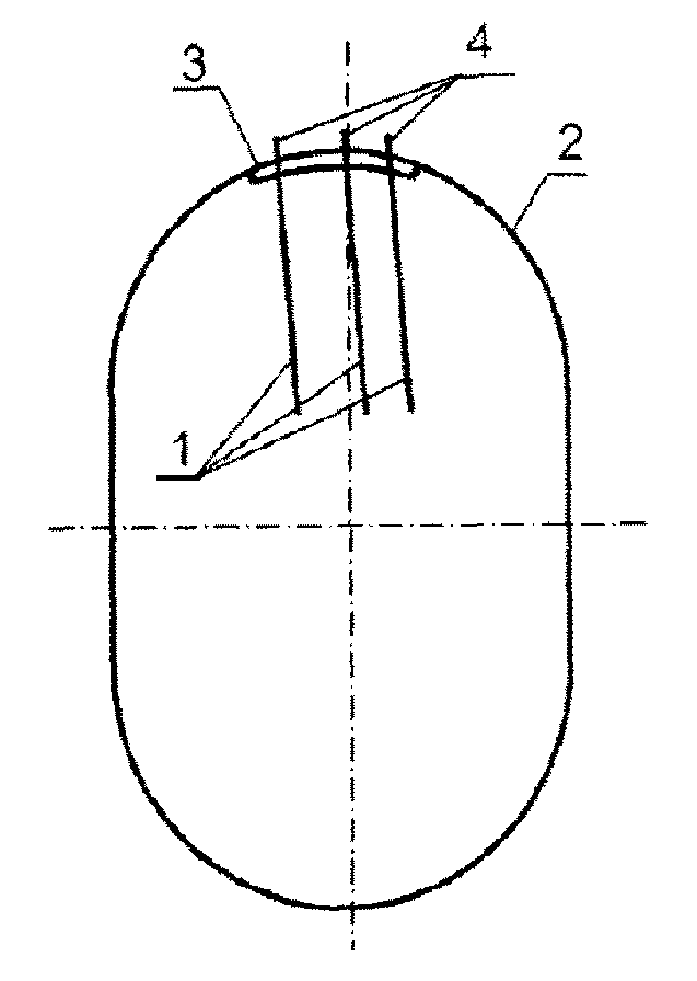
Figure 1 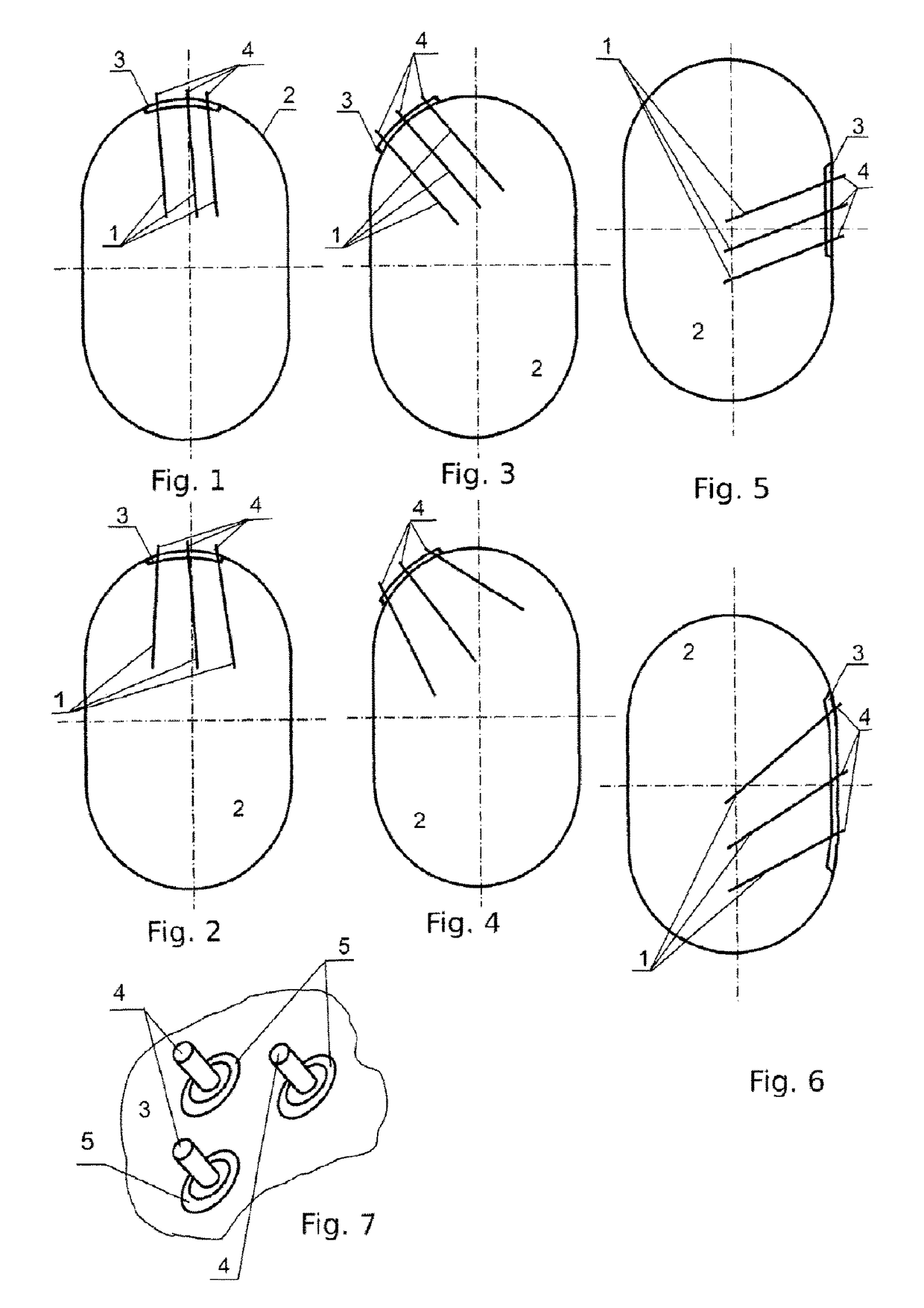
Figure 2 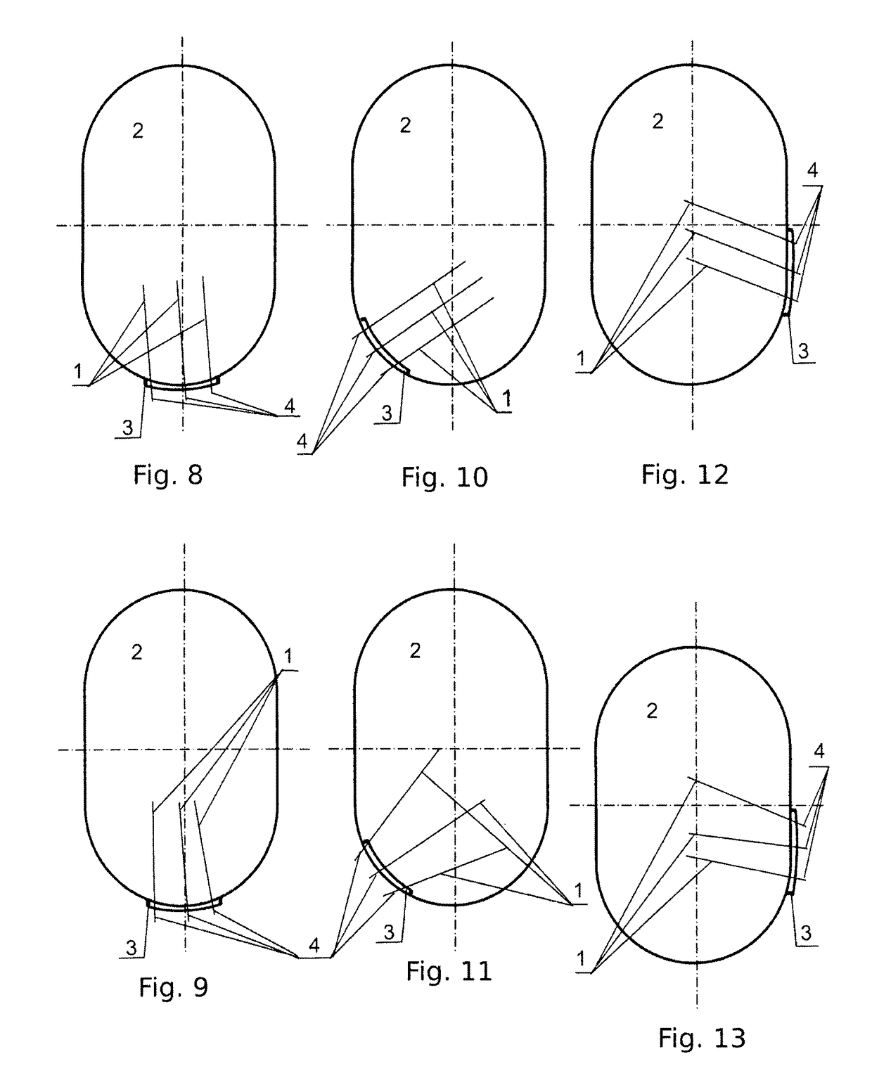
Figure 3
Abstract
Description
FIELD OF THE INVENTION
[0001] The invention relates to heat engineering, power engineering and the field of electric heating of liquids, water for instance, steam generation, direct conversion of electric energy into heat energy; it can be used in circulation water heating systems, self-regulating liquid heaters for autonomous heating and hot water supply, mobile heating and hot water supply, and as a universal device for diverse electric heaters.BACKGROUND OF THE INVENTION
[0002] Electrode water heating boilers are designed to provide hot water and steam at the expense of heat released by electric current (single- or three-phase one) directly flowing through water. Boilers are used for heating and hot water supply of production and residential spaces, in open as well as close heating systems. They are also used at industrial plants, agricultural plants, and any other facilities which manufacturing processes require hot water of 95 . . . 100 Celsius degrees. The simple design, high reli...
Examples
embodiment 1
[0063]FIGS. 1 . . . 7, 14 . . . 28 represent a view of configuration of electrode boiler with multiple electrode according to Embodiment 1 of this invention.
[0064]As per Embodiment 1, electrodes 1 of the device, at least one or more electrodes are directed inside the case 2 downwards. In FIG. 1, electrodes 1 are directed straight down, the longitudinal axes of all the electrodes 1 slightly deviating from the longitudinal symmetric axis of case 2. Electrodes 1 if used more than one in number may be installed at different unequal distances to each other (FIG. 1). Longitudinal axes of part or of all electrodes 2 may also form nonzero angles against each other as shown in FIG. 2 accompanied by unequal distances between electrodes 1. Electrodes 1 are located at basis 3 which may be installed both inside case 2, as shown in FIGS. 1-2, 5-6, and outside—FIGS. 3-4. Each electrode 1 has terminal 4 running through basis 3 and case 2 to be connected to an electric power supply. Basis 3 may be i...
embodiment 2
[0073]FIGS. 8-28 represent a view of electrode boiler with multiple electrode configuration according to Embodiment 2 of the invention in question. Embodiment 2 has the following specific aspects as compared to Embodiment 1.
[0074]As per Embodiment 2, electrodes 1 of the device, at least one electrode or more, for example two or three for a three-phase electric mains, or in number multiple of 3 for a three-phase electric mains—are directed into case 2 upwards. In FIG. 8 electrodes 1 are directed upwards vertically with the longitudinal axes of all electrodes 1 slightly deviating from the longitudinal symmetric axis of case 2. Electrodes 1, if used in number exceeding one, may be installed at different unequal distances from each other (FIG. 8). The longitudinal axes of electrodes may also make non-zero angles against each other for all electrodes 2 or a part of them as shown in FIG. 9; this being accompanied with unequal distances between electrodes 1 at the same time. Electrodes 1 a...
embodiment 3
[0079]FIGS. 29-36 represent a view of configuration of an electrode boiler with multiple electrode according to Embodiment 3 of this invention. Embodiment 3 has the following specific aspects as compared to Embodiments 1 and 2.
[0080]As per Embodiment 2, electrodes 1 of the device, at least one electrode or more, for example two or three for a three-phase electric mains, or in number multiple of 3 for a three-phase electric mains, or in any required number, generally all used in a concrete specimen of the device, are fastened directly in case 2 without any basis. Such an implementation of the device provides (FIG. 29) fastening of electrodes 1 through dielectric insulating heat-resistant inserts 5 directly pressed into the wall of case 2 or its cover. Here, terminals 4 of electrodes 1 for connection of an electric power supply are brought outside from the device case 2.
[0081]Electrodes 1 may be grouped at the same point of boiler case similarly to Embodiments 1, 2 or distributed on t...