
Low-voltage-difference voltage-stablizer
A low-dropout linear, voltage-stabilizer technology, applied in instruments, control/regulating systems, regulating electrical variables, etc., can solve the problem that LDO circuits cannot simultaneously achieve high output voltage accuracy, high stability and high power supply voltage rejection ratio, etc. Achieve the effect of overcoming system stability reduction, low output noise, and ensuring stability
- Summary
- Abstract
- Description
- Claims
- Application Information
AI Technical Summary
Problems solved by technology
Method used
Image

Examples
Embodiment Construction
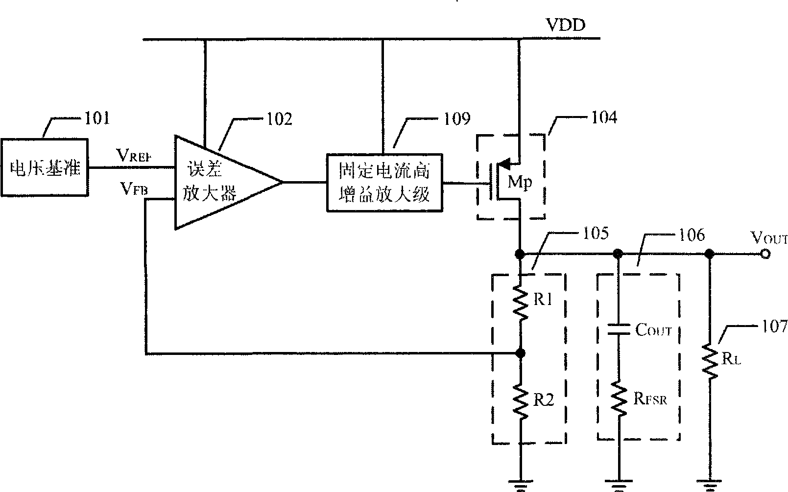
[0044] Figure 5 A typical LDO principle block diagram of the present invention is given. The LDO is composed of a voltage reference circuit 101, an error amplifier 102, a variable transconductance filter circuit module 302, a variable current high-gain amplifier stage 103 (the current flowing through this stage increases with the increase of the LDO load current), a power tube 104 , a voltage dividing sampling network 105 , an output capacitor 106 and a load 107 . its with image 3 The difference of the shown circuit is that the fixed current high gain amplifier stage 109 is replaced by the variable current high gain amplifier stage 103, and a variable current high gain amplifier stage 109 is added between the output terminal of the error amplifier 102 and the input terminal of the variable current high gain amplifier stage 103. A filter circuit module 302 with variable transconductance.
[0045] The filter circuit module 302 of the variable transconductance is made up of ...
PUM
 Abstract
Description
Claims
Application Information