Card connector

A card connector and card insertion technology, applied in the direction of connections, instruments, and parts of connection devices, etc., can solve the problem that the card cannot be locked, reduce the width and height of the card connector 201, and reduce the width and height of the card connector 101 and other problems, to achieve the effect of reducing the depth size and size

Inactive Publication Date: 2009-08-19
TYCO ELECTRONICS JAPAN GK
View PDF7 Cites 0 Cited by
  • Summary
  • Abstract
  • Description
  • Claims
  • Application Information

AI Technical Summary

Problems solved by technology

[0011] especially in Figure 13 In the case of the shown card connector, although the width and height of the card connector 101 can be reduced since the cam groove 112 is formed near the card insertion opening of the housing 110, there is a problem in that it is difficult to reduce the size of the card connector 101. Dimensions in the depth direction (direction of card insertion and ejection)
[0012] Also, in the case of the card connector 101, there is no means of effectively locking the card
Therefore, the card cannot be locked in the state where the card insertion has been completed
In addition, there is also the problem of not being able to prevent the card from popping out when the card is ejected
[0014] But also in the card connector 201, although the width and height of the card connector 201 can be reduced since the cam groove 112 is formed near the card insertion opening of the housing 210, there is a problem in that it is difficult to reduce the depth of the card connector 201. direction size

Method used


Image

  • Card connector
  • Card connector
  • Card connector

Examples


Embodiment Construction

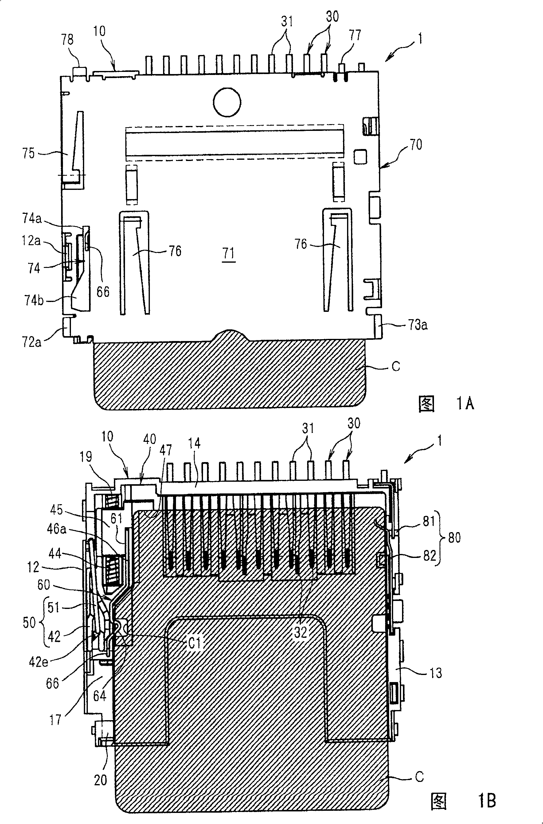
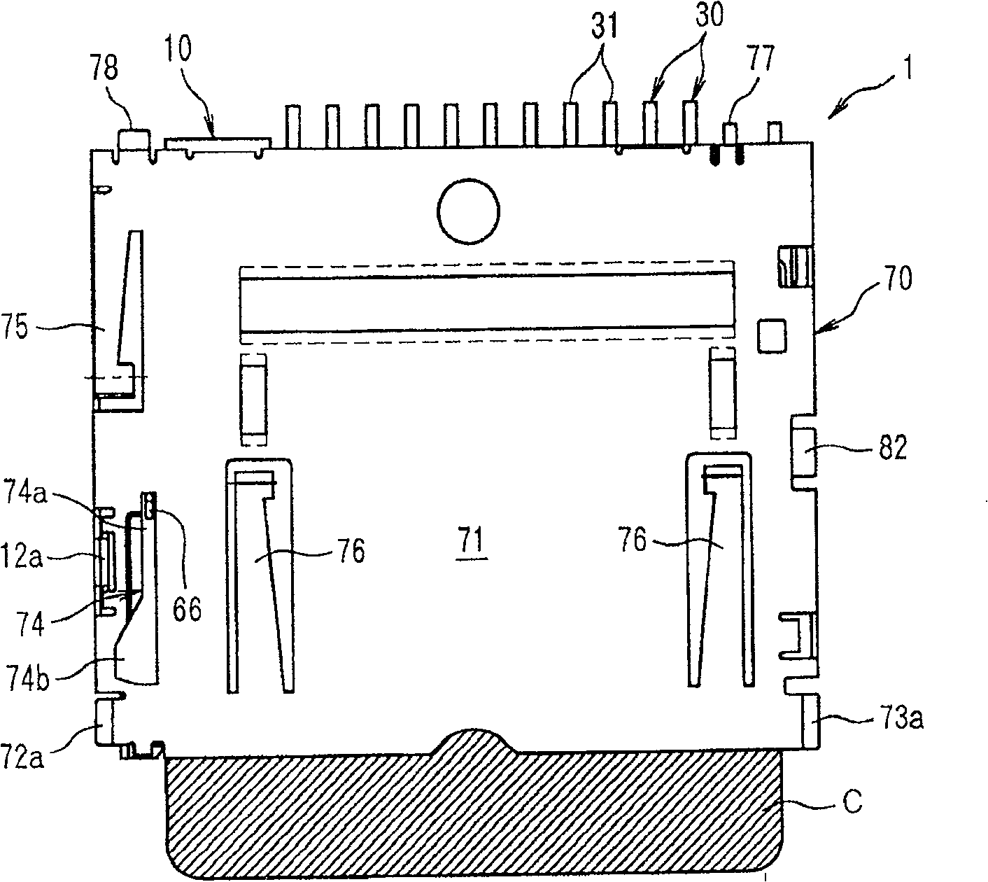
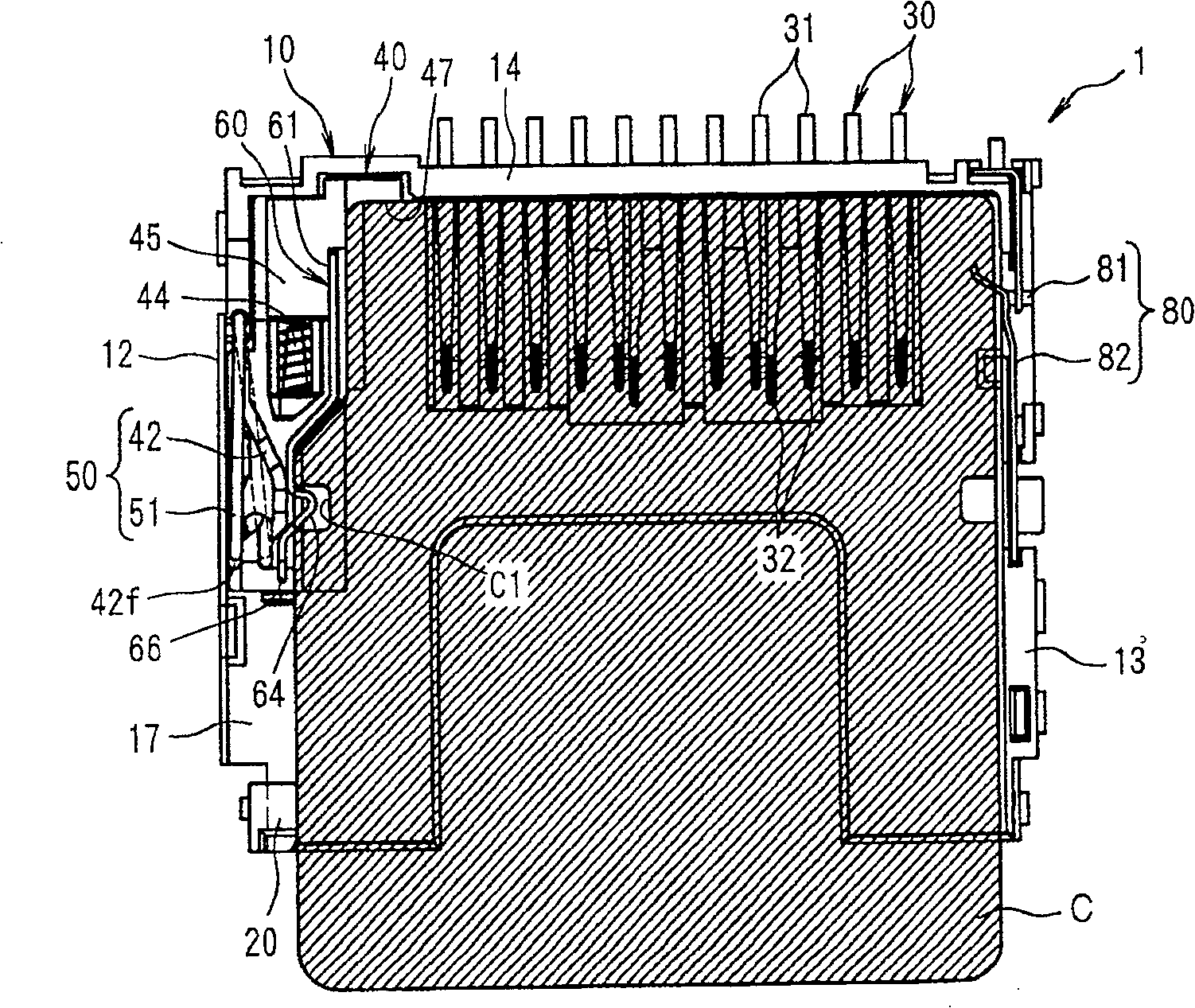
[0037] Next, embodiments of the present invention are described with reference to the drawings. Figure 1A and 1B Indicates the state that the card is inserted into the card connector of the present invention, and the insertion has been completed, wherein Figure 1A is a planar graph, and Figure 1B is the plan view with the cover removed. Figure 2A and 2B Indicates that the card is from Figure 1A and 1B The state shown is inserted into the state at the rearmost end position, where Figure 2A is a planar graph, and Figure 2B is the plan view with the cover removed. Figure 3A and 3B Indicates that the card is from Figure 2A and 2B The state shown pops up, where Figure 3A is a planar graph, and Figure 3B is the plan view with the cover removed. Figures 4A-4C express Figure 1A and 1B the card connector, which Figure 4A is the floor plan, Figure 4B is the front view, and Figure 4C is the rear view. Figure 5A and 5B express Figure 1A and 1B the c...


PUM


Abstract

A card connector (1), wherein a cam mechanism (50) is composed of a heart-shaped cam groove (42) that is formed in a slider (40), and a cam rod (51) that is shaft-supported by a housing (10) and that swings along the cam groove (42). A locking member (60) has a cantilever form one end of which is fastened to the slider (40), and the mobility range of the free end at the other end overlaps with the cam groove (42).

Description

technical field [0001] The present invention relates to a card connector for connection with a card such as a memory card. Background technique [0002] In recent years, card-operated electronic devices have rapidly become popular, in which a card such as a memory card that a user has is inserted into an electronic device such as a camera, a personal computer, and a mobile phone as needed, and data is recorded from the electronic device on the card. on, or data is supplied from the card to the electronic device. [0003] Such a card-operated electronic device is provided with a card connector for connecting with a card such as a memory card. [0004] For example Figure 13 The card connector shown (see JP2000-251025A) is already known as a conventional card connector of this type. [0005] This card connector 101 includes a housing 110 in which a card (not shown in the drawings) is inserted and has a plurality of contact support grooves 111, arranged on one side of the hou...

Claims


Application Information

Patent Timeline
Patent Type & Authority Patents(China)
IPC IPC(8): H01R13/633H01R13/639G06K17/00G06K13/08
CPCG06K13/0856G06K13/08H01R12/71
Inventor 辻淳也
Owner TYCO ELECTRONICS JAPAN GK
Why Eureka
Try Eureka