Selective protection switch

A selective, switching technology, applied in the direction of adjusting protection switch conditions, overload protection circuit breaker, protection switch operation/release mechanism, etc. Selective protection, simple switching circuit, saving production time

Active Publication Date: 2009-12-23
ZHEJIANG CHINT ELECTRIC CO LTD
View PDF5 Cites 0 Cited by
  • Summary
  • Abstract
  • Description
  • Claims
  • Application Information

AI Technical Summary

Problems solved by technology

Conventional current-limiting resistors use ordinary alloy resistance wires to be wound into coils. The coils generate a strong magnetic field and need to be wound in reverse and in parallel. The process is quite complicated.
Moreover, in order to avoid short circuit between windings, the resistance wire needs to be specially insulated, which increases the cost, and the final formed current-limiting resistor has a large volume, which is very inconvenient to use.
In order to avoid this problem, some existing technologies use a current-limiting resistor of a special material to be connected in parallel to the current path, such as a resistor of a ceramic material with a constant or negative temperature coefficient. In order to achieve a good effect on this current-limiting resistor The requirements are relatively strict, the processing materials are more complicated, and the sintering process is more complicated, which increases the cost

Method used


Image

  • Selective protection switch
  • Selective protection switch
  • Selective protection switch

Examples


Embodiment Construction

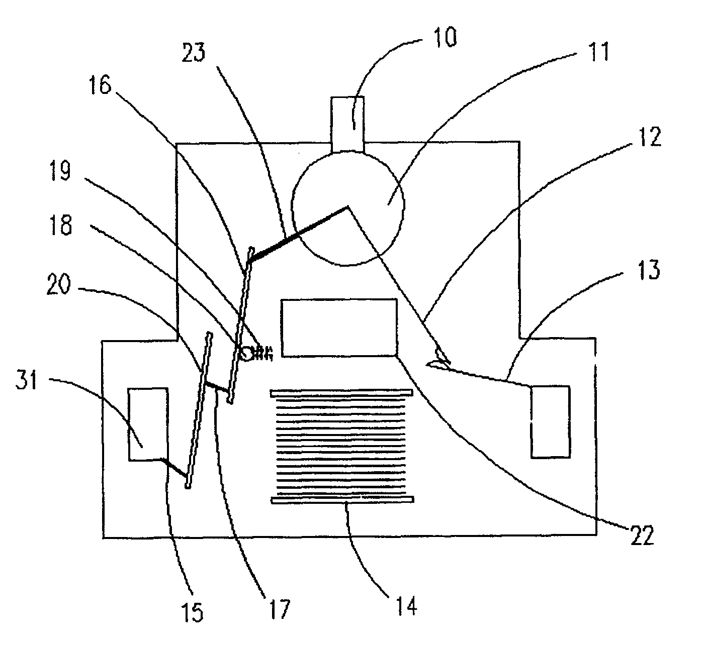
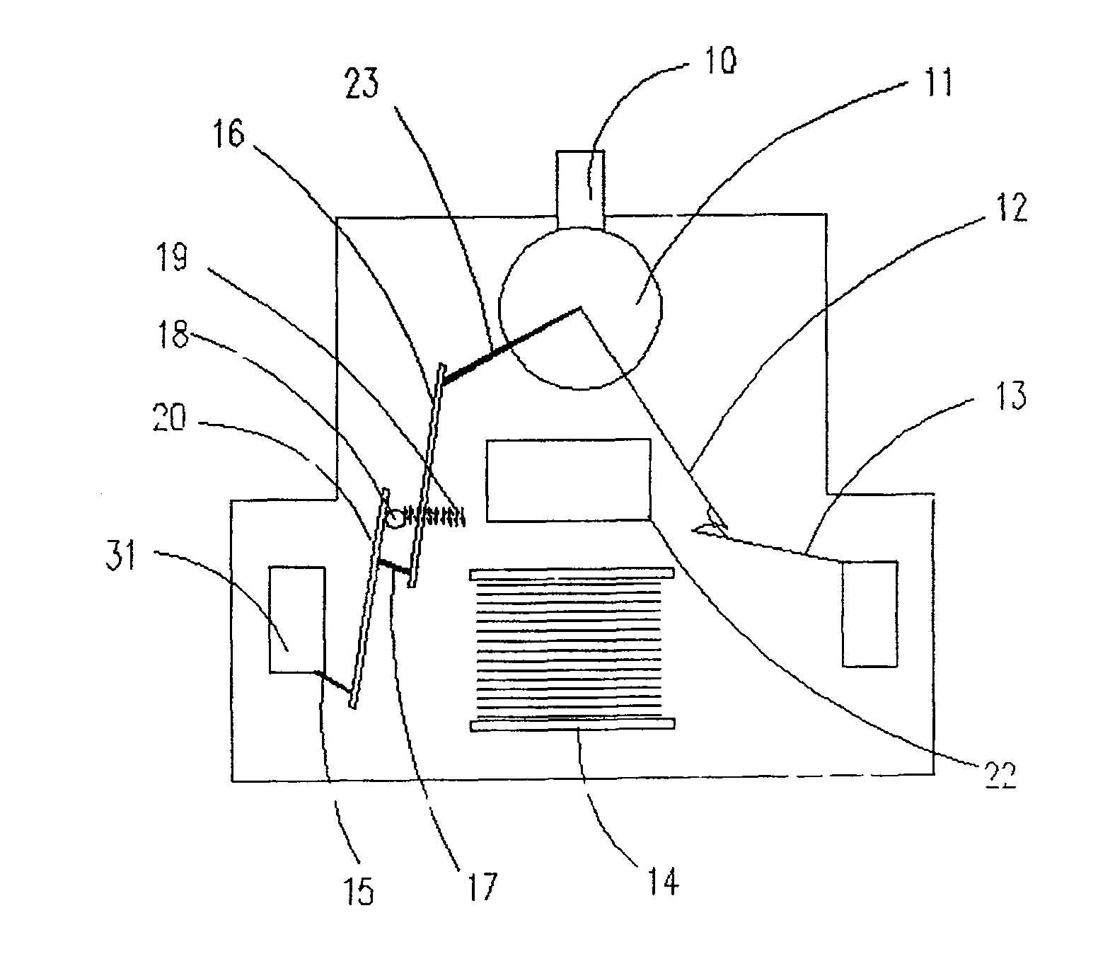
[0017] The specific implementation of the selective protection switch of the present invention will be further described in detail below in conjunction with the specific embodiments of the present invention shown in the accompanying drawings.

[0018] Such as figure 1 , figure 2 As shown, the selective protection switch of the present invention is arranged in a housing, for example, two nearly symmetrical half housings are riveted to form a whole. An operating handle 10 is arranged on the housing, and the operating handle cooperates with an operating mechanism 11 in the housing to control the closing and opening of the movable contact 12 and the static contact 13 in the housing. That is, when the operating handle 10 closes the switch, the circuit is connected; when the operating handle 10 turns off the switch, the circuit is cut off. Once a fault occurs, the switch will disconnect the circuit, and at this time, the arc will be introduced into the arc extinguishing chamber 1...


PUM


Abstract

A switch with selective protection function, comprising a trip rod (18), a first temperature sensing element (16), a second temperature sensing element (20) and an electromagnetic mechanism (22). Wherein, the tripping rod is movably arranged in the switch; the electromagnetic mechanism pushes the tripping rod when the circuit is short-circuited, so that the tripping rod moves from the first temperature-sensing element to the second temperature-sensing element, and keeps At the position of the second temperature sensing element. When the circuit is overloaded, the first temperature-sensing element pushes the trip lever to disconnect the switch after a delay; when the circuit is short-circuited, the second temperature-sensing element acts to push the trip lever to disconnect the switch; the first temperature-sensing element It is connected in series with the second temperature sensing element, and also includes a trip lever position reset mechanism. When the circuit is disconnected due to a short circuit, the reset mechanism resets the trip lever to correspond to the first temperature sensing element s position. The invention realizes the selective protection of the circuit during overload and short circuit by adopting common thermal sensitive element and simple selection device.

Description

technical field [0001] The invention relates to a switchgear, in particular to a switch with selective protection function. The switch is generally used in the technical fields of power transmission and distribution, generators, and electrical control, such as current switching equipment such as load switches, circuit breakers, and contactors, and their supplementary electrical equipment. Background technique [0002] The current selective switch equipment is widely used. For example, in the power distribution system, in order to reduce the power outage range once the line or equipment fails, it is required to only cut off the power of the faulty line, and the other lines are still powered normally, which requires protection. The superior switch has a selective protection function. [0003] The current selective protection is divided into current selectivity, time selectivity and energy selectivity. The current selectivity is realized by the different action currents of th...

Claims


Application Information

Patent Timeline
Patent Type & Authority Patents(China)
IPC IPC(8): H01H73/00H01H73/22H01H71/14H01H71/74
Inventor 汪泰宇段育明
Owner ZHEJIANG CHINT ELECTRIC CO LTD
Why Eureka
Try Eureka