Ultrahigh-frequency testing device for transponders

A technology of testing equipment and transponders, which is applied to record carriers, instruments, measuring devices, etc. used in machines, can solve problems such as lack of reference information, and achieve the effect of simple failure analysis

Inactive Publication Date: 2007-08-08
MUEHLBAUEHR AG
View PDF0 Cites 1 Cited by
  • Summary
  • Abstract
  • Description
  • Claims
  • Application Information

AI Technical Summary

Problems solved by technology

Therefore, due to interference effects, or lack of reference information about the identification data of a certain transponder, it is possible to assign erroneous measurements to a specific transponder arranged on the support

Method used


Image

  • Ultrahigh-frequency testing device for transponders

Examples


Embodiment Construction

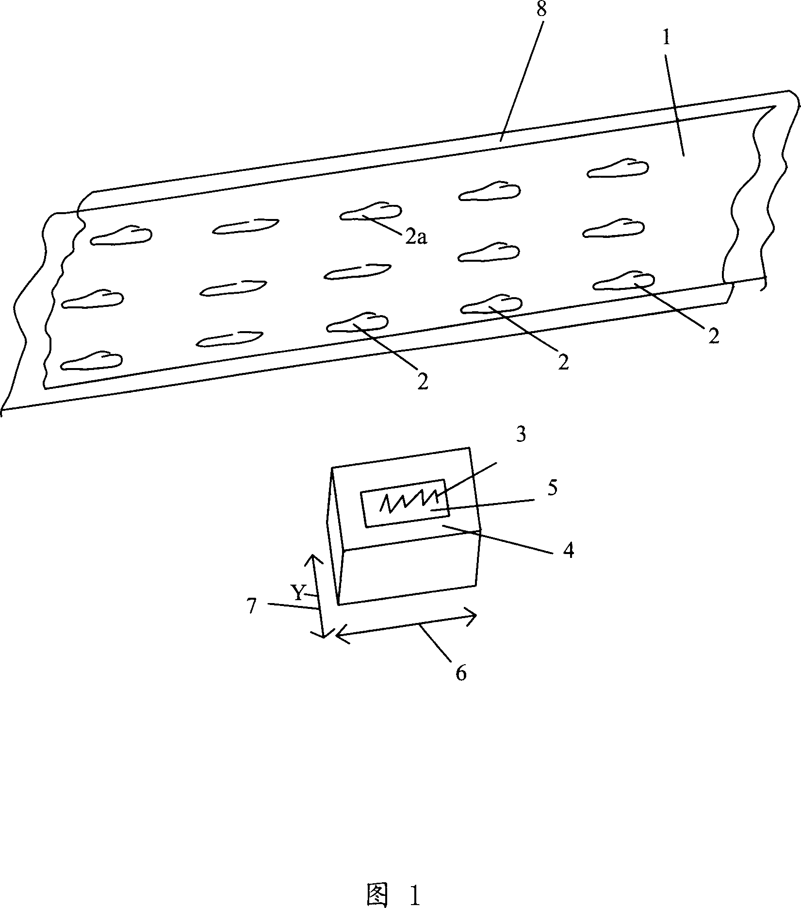
[0022] According to the embodiment shown in the drawings, a plurality of transponders, 2a, are arranged on a plate-like or strip-shaped common support 1, and each transponder is distributed front-to-back and / or adjacent to each other.

[0023] A UHF antenna element 3 with a shielding shell 4 is arranged below the planar support 1 . The shielding case 4 is designed for shielding UHF waves. The shielding case 4 surrounds the antenna element 3 such that the opening 5 on the top surface of the shielding case 4 faces the underside of the support 1 . The opening 5 allows the measurement area of ​​the antenna element 3 to be aimed in the direction of the selected transponder 2a without affecting other transponders adjacent to the selected transponder 2a.

[0024] The shielding shell 4 is movable in the x-direction and the y-direction in a plane parallel to said supporting surface, as indicated by arrows 6 and 7 . In this way, the antenna element can be driven to aim at each success...


PUM


Abstract

The invention relates to an ultrahigh-frequency testing device for transponders that are two-dimensionally disposed behind and/or next to each other on or in an area of a joint support. Said testing device is used for checking ultrahigh-frequency functions and other transponder (2) data by means of at least one ultrahigh-frequency antenna element (3). Said antenna element (3) is located within a shielding housing (4) which acts in an isolating manner on ultrahigh-frequency waves and is provided with an opening (5) that faces a selected transponder (2) which is to be checked. Said opening (5) has an area that is adapted to the basal surface of the transponder (2).

Description

technical field [0001] According to the preamble of claim 1, the present invention relates to a UHF detection device for transponders arranged one behind the other and / or adjacent to each other in a mesh-like manner. On the surface of the common support and / or in the common support, the detection device is used to detect the UHF function of the transponder and other data by means of at least one UHF antenna element. Background technique [0002] Transponders based on RFID (Radio Frequency Identification) operating in the Ultra High Frequency (UHF) range are usually mass-produced in the form of web structures (web). The network structure comprises a large number of transponders arranged one behind the other and adjacent to each other on a common planar support. These transponders typically operate at very high frequencies, as well as in higher frequency ranges. [0003] During manufacture, in order to test the function of the transponders arranged in this way, the antenna e...

Claims


Application Information

Patent Timeline
Patent Type & Authority Applications(China)
IPC IPC(8): G01S7/40G01S13/75H01Q1/52G06K17/00G01R31/302H04B17/00G06K19/077
Inventor 朱根·萨斯沃尔克·布罗德
Owner MUEHLBAUEHR AG
Why Eureka
Try Eureka