Lighting system and projector

A lighting system and projection device technology, applied in projection devices, optics, instruments, etc., can solve problems such as loss of beam brightness, reduction of light utilization efficiency, and failure to meet design requirements, and achieve the best convergence effect

Inactive Publication Date: 2007-10-10
CORETRONIC
View PDF0 Cites 12 Cited by
  • Summary
  • Abstract
  • Description
  • Claims
  • Application Information

AI Technical Summary

Problems solved by technology

However, the etendue value of the projection device depends on the specifications of the light valve used (for example: digital micro-mirror device (Digital Micro-mirror Device, DMD)), and the etendue provided by the existing lighting system is greater than the value required by the DMD, so it will The light utilization efficiency is reduced, and the brightness of the light beam provided by the lighting system is lost, making it impossible to improve the brightness of the projection device
[0006] In addition, since the parallel light beams 112a, 122a directly irradiate the second and first lamps 120, 110 respectively, and repeatedly pass through the wicks 112, 122, it is easy to cause the wicks 112, 122 to overheat and be damaged.
Moreover, if one of the lamps breaks down, half of the images projected by the projection device will be darker.
In addition, the structure of the dual-lamp lighting system 100 is relatively large, which makes the projection device relatively bulky. Under the current trend of pursuing short, light and thin electronic products, the dual-lamp lighting system 100 with this structure obviously does not meet the current design requirements.

Method used


Image

  • Lighting system and projector
  • Lighting system and projector
  • Lighting system and projector

Examples


Embodiment Construction

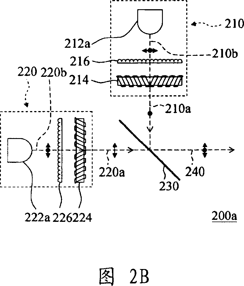
[0039] Please refer to FIG. 2A , the lighting system 200 of the present invention includes a first polarized light source 210 , a second polarized light source 220 and a polarized beam splitting element 230 . The first polarized light source 210 is adapted to provide a first light beam 210a with a first polarization direction, and the second polarized light source 220 is adapted to provide a second light beam 220a with a second polarization direction, wherein the second The polarization direction is perpendicular to the first polarization direction, and the first light beam 210a and the second light beam 220a can be linearly polarized light, circularly polarized light or elliptically polarized light. In this embodiment, the first light beam 210a and the second light beam 220a are linearly polarized light, the first polarization direction is the vertical direction, and the second polarization direction is the horizontal direction, and the first polarized light source 210 and the...


PUM


Abstract

An illumination system is prepared for using the first bias-polarized light source to provide the first light beam with the first polarization direction and using the second one to provide the second light beam with the second polarization direction, making two said polarization directions be orthogonalized to each other, setting polar biased spectral element at light path cross point of two said light beams to reflect the first light beam and to let the second light beam pass then making reflected first light beam be overlapped with passed second light beam. The projection device applying said system is also disclosed.

Description

technical field [0001] The present invention relates to an illumination system and a projection device, in particular to an illumination system and a projection device with multiple light sources. Background technique [0002] With the advancement of optical projection technology, projection devices capable of outputting high-quality and high-brightness images have been developed and widely used. A projection device is mainly composed of a lighting system, a light valve, and an imaging system, and the intensity of the light source provided by the lighting system is often an important key that affects the brightness of the projected image. Therefore, improving the lighting system has become an important research topic . [0003] Please refer to FIG. 1 , the dual-lamp lighting system 100 disclosed in U.S. Patent No. 6,196,699 includes a first lamp 110, a second lamp 120 and a reflector 130, wherein the first lamp 110 is opposite to the second lamp 120, and the second The opt...

Claims


Application Information

Patent Timeline
IPC IPC(8): G03B21/14G03B21/00G02B27/28
Inventor 陈科顺
Owner CORETRONIC
Why Eureka
Try Eureka