Light-conducting element and sensing component possessing same

A technology of light guide components and components, which is applied in the field of photoelectric mouse, and can solve the problems of beam 112 convergence, beam 112 easy to diverge, consumption, etc.

Inactive Publication Date: 2008-06-04
ELITE ADVANCED LASER CORP
View PDF0 Cites 0 Cited by
  • Summary
  • Abstract
  • Description
  • Claims
  • Application Information

AI Technical Summary

Problems solved by technology

[0005] In the above-mentioned sensing component 100, since the light beam 112 provided by the light emitting diode 110 needs to be reflected by the reflective surfaces 132, 134 before being projected onto the desktop 60, the light path of the light beam 112 is relatively long.
In addition, since the reflective surfaces 132 and 134 cannot converge the light beam 112 provided by the light emitting diode 110 into an ideal parallel light, the light beam 112 is easier to diverge during the transmission process, and the light path of the light beam 112 is longer, resulting in projection The energy of the light beam 112 on the CMOS image sensor 120 is low
In other words, the light utilization efficiency of the existing sensing component 100 is poor
In addition, since the light utilization efficiency of the sensing component 100 is poor, in order to maintain the sensitivity of the photoelectric mouse, it is necessary to increase the luminous power of the light emitting diode 110, but this will consume more energy.

Method used


Image

  • Light-conducting element and sensing component possessing same
  • Light-conducting element and sensing component possessing same
  • Light-conducting element and sensing component possessing same

Examples


Embodiment Construction

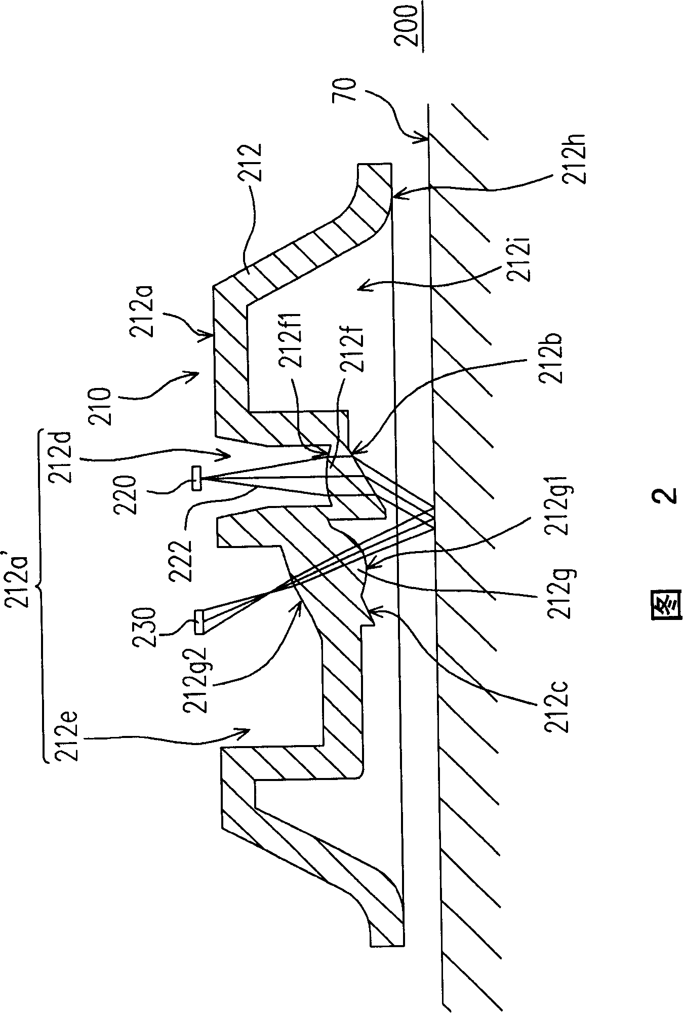
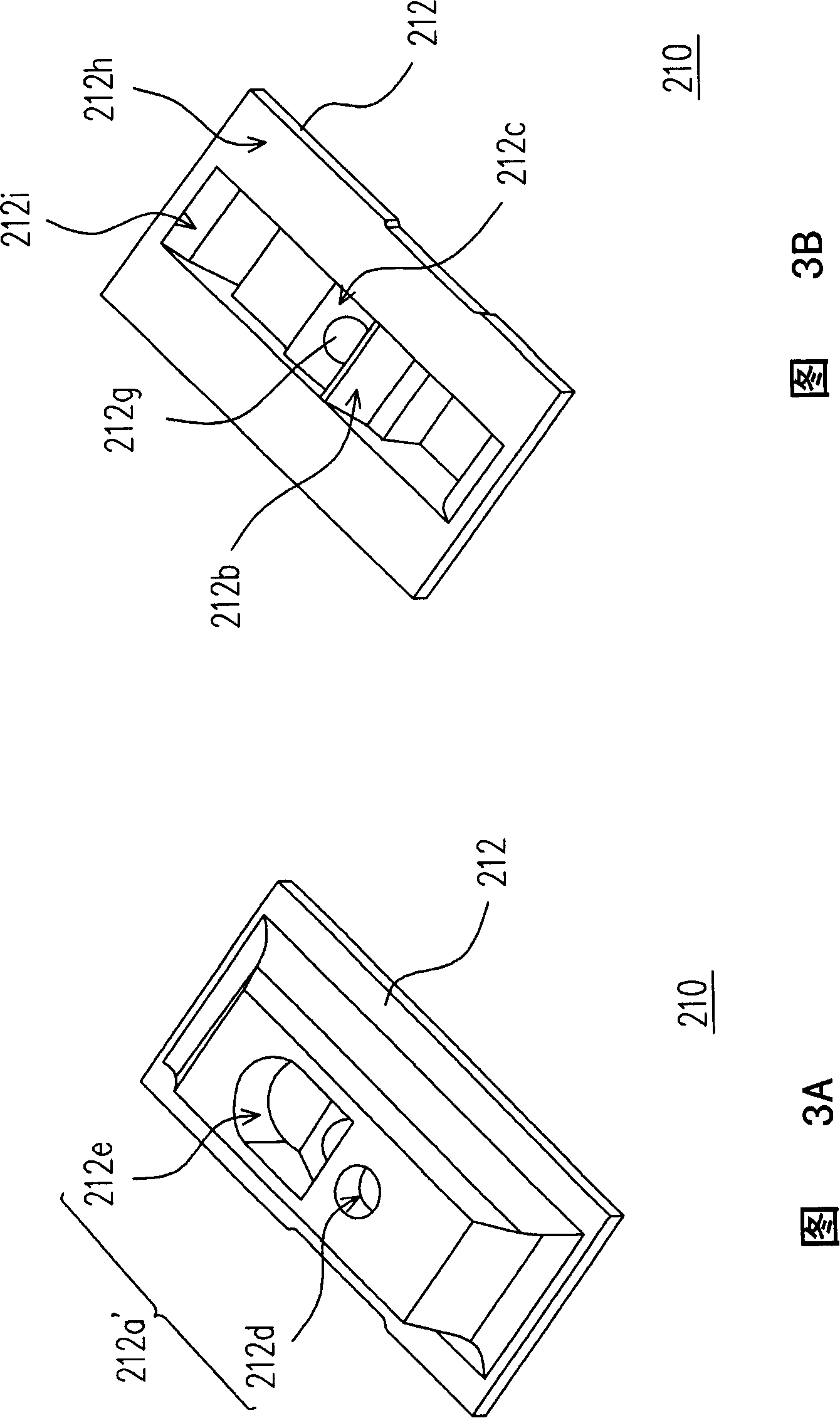
[0032] FIG. 2 is a schematic diagram of a sensing component according to an embodiment of the present invention, and FIGS. 3A and 3B are perspective views of the light guide element in FIG. 2 from different perspectives. Please refer to FIG. 2 , FIG. 3A and FIG. 3B , the sensing component 200 of this embodiment is suitable for an optical mouse. The sensing component 200 includes a light guide element 210 , a light source 220 and an image sensing element 230 . The light guide element 210 includes a main body 212 , and the main body 212 has a top plane 212 a and a first inclined surface 212 b and a second inclined surface 212 c at the bottom of the main body 212 . A concave portion 212a' is formed on the top plane 212a, and a first lens portion 212f is formed at the bottom of the concave portion 212a'. The first slope 212b is opposite to the first lens portion 212f, and the second slope 212c is opposite to the bottom of the concave portion 212a', and a second lens portion 212g ...


PUM


Abstract

The invention discloses a light guide element for an optical mouse. The light guide element comprises a body provided with a cap plane, a first bevel positioned at the bottom of the body and a second bevel, wherein, the cap plane is provided with a sunken part, a first lens part is formed at the bottom of the sunken part, the first bevel is opposite to the first lens part, while the second bevel is opposite to the bottom of the sunken part; moreover, a second lens part is formed on the second bevel. In addition, a light source and an image sensing element are arranged above the sunken part and the light source provides a beam of light to the first lens part. The beam of light is converged by the first lens part and is refracted on the surface of the first bevel through the first bevel, while the surface is suitable for refracting the beam of light to the second lens part and an image of the beam of light is formed on the image sensing element by the second lens part.

Description

technical field [0001] The present invention relates to an optical mouse, and in particular to a sensing component and a light guide element of the optical mouse. Background technique [0002] The optical mouse has replaced the mechanical mouse and has become the mainstream in the mouse market due to its advantages of precise positioning, no need for moving parts, and low failure rate. [0003] Generally speaking, an optical mouse has a sensing component, which includes a light source, an image sensor (image sensor) and a light guide component, wherein the light source is a light emitting diode (light emitting diode, LED) or a laser (laser), and The image sensing element is a complementary metal oxide semiconductor (CMOS) image sensing element. In addition, the light guide element is used to guide the light beam provided by the light source to a specific area on the surface where the optical mouse is placed, and focus the light beam reflected from the specific area onto the...

Claims


Application Information

Patent Timeline
Patent Type & Authority Applications(China)
IPC IPC(8): G06F3/033G02B6/00G06F3/0354
Inventor 郑祝良王继华沈映典
Owner ELITE ADVANCED LASER CORP
Why Eureka
Try Eureka