Scanning backlight for LCD

A technology of backlight device and backlight unit, which is applied in optics, nonlinear optics, instruments, etc., and can solve problems such as motion blur

Inactive Publication Date: 2007-12-19
KONINK PHILIPS ELECTRONICS NV
View PDF1 Cites 2 Cited by
  • Summary
  • Abstract
  • Description
  • Claims
  • Application Information

AI Technical Summary

Problems solved by technology

[0002] LCD (Liquid Crystal Display) panels suffer from motion blur due to their sample-and-hold nature, i.e. the LC (liquid crystal) remains in the same state during the entire frame after addressing

Method used


Image

  • Scanning backlight for LCD
  • Scanning backlight for LCD
  • Scanning backlight for LCD

Examples


Embodiment Construction

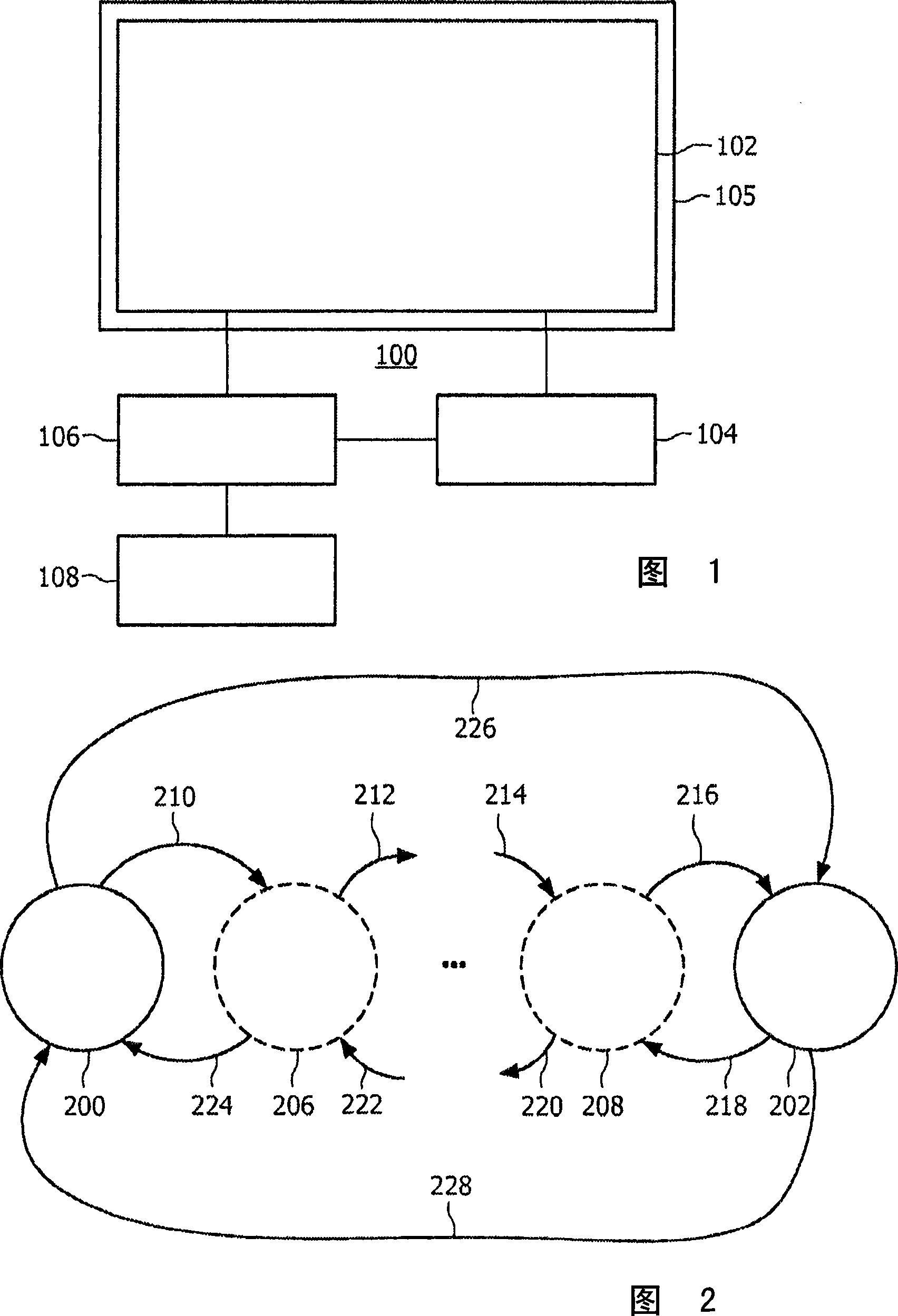
[0034] FIG. 1 illustrates a display 100 including a display panel 102 . The display panel 102 , which may be an LCD (Liquid Crystal Display) panel, has a backlight 105 . The backlight arrangement 105 may, for example, include one or more light sources (not shown), such as light emitting diodes (LEDs) or gas discharge lamps. The backlight shines on the entire panel 102 or better by scanning the backlit portion of the panel 102 . Thus, the LC cells are illuminated only for a certain part of the frame period. A backlight controller 104 connected to a backlight device 105 of the panel 102 controls the blinking of the backlight. To avoid large areas of flicker, the backlight controller 104 provides backlight control signals depending on the image displayed on the panel 102 . Accordingly, backlight controller 104 is connected to display controller 106 which in turn receives image data from image data source 108 . It should be noted that this description is for illustrative purpo...


PUM


Abstract

A method for displaying images on a display having backlight is disclosed, where the images is updated periodically with a period. The method comprises the steps of: generating a signal with a pulse pattern for each period depending on the contents of an image to be displayed in that period; and activating backlight in accordance with the signal. Further, a display (100) comprising a display panel (102) and a backlight unit, wherein the backlight unit comprises a controller (104) and a lighting device is disclosed. The controller (104) is arranged to generate a control signal, and the lighting device is arranged to provide backlight to the display panel (102) according to the control signal, wherein the control signal comprises a pulse pattern depending on contents of displayed images.

Description

technical field [0001] The present invention relates to a method for generating backlight according to the contents of displayed images and a display device for generating backlight according to the contents of displayed images. Background technique [0002] LCD (Liquid Crystal Display) panels suffer from motion blur due to their sample-and-hold characteristics, ie the LC (Liquid Crystal) remains in the same state during the entire frame after addressing. When a displayed object moves, as is often the case in eg television images, this results in a blurred image of the object on the viewer's retina. In US patent US2004 / 0012551A is disclosed a device for driving data whose value corresponds to the display data of the current frame. By comparing with the display data of the previous frame, the display data in the changed current frame is enhanced by an amount larger than the pixel data and written into the LCD driver. Also, a backlight control device is disclosed, which is u...

Claims


Application Information

Patent Timeline
Patent Type & Authority Applications(China)
IPC IPC(8): G09G3/34
CPCG09G2320/0247G09G2320/062G09G2320/064G09G2320/106G09G3/342G09G2320/0261G09G2320/0633G09G2310/024G02F1/133G09G3/34
Inventor R·范沃登伯格H·W·格鲁特胡尔泽J·H·C·J·斯特森A·塞沃G·J·赫克斯特拉H·J·布兰克斯V·科瓦塞维克J·登布里詹
Owner KONINK PHILIPS ELECTRONICS NV
Why Eureka
Try Eureka