
Sliding bracket for automobile lamp fixture mounting groove
A technology for automobile lamps and sliding brackets, which is applied to lighting devices, fixed lighting devices, electric light sources, etc., can solve the problems of difficult to ensure installation accuracy, surface difference, gap between lamps and vehicle bodies, etc., and achieves reliable performance, convenient adjustment, simple structure
- Summary
- Abstract
- Description
- Claims
- Application Information
AI Technical Summary
Problems solved by technology
Method used
Image

Examples
Embodiment Construction
[0011] The present invention will be described in detail below in conjunction with the accompanying drawings and embodiments.
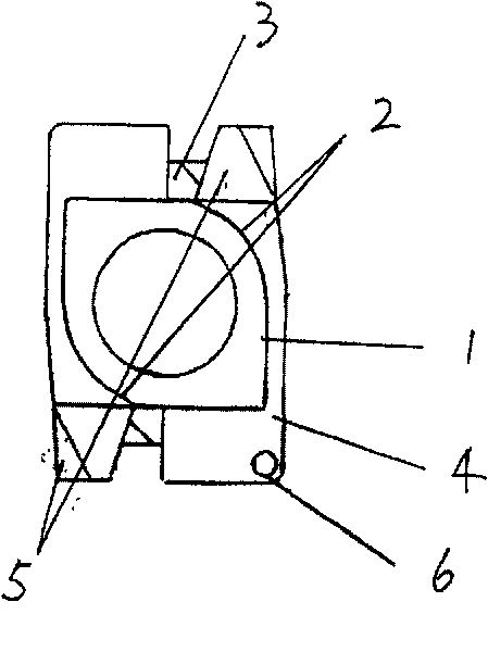
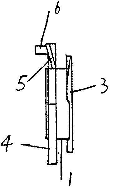
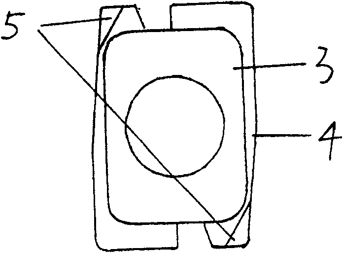
[0012] It includes a pin 1, which is characterized in that the cross section of the pin 1 is a square, two of the opposite corners of the square are replaced by two inscribed arcs 2 of the square, and the bottom of the pin 1 is provided with a first rectangular Baffle plate 3, the top of this pin 1 is provided with the second baffle plate 4, the width of the second baffle plate 4 is greater than the width of the first rectangular baffle plate 3, the length of the first rectangular baffle plate 3 and the second baffle plate 4 are equal Greater than the width of the first rectangular baffle 3, the second baffle 4 is provided with two wing-type guide pieces 5 corresponding to the two inscribed arcs 2 of the pin, and the outer sides of the wing-type guide pieces 5 are tilted upward. An upwardly protruding pre-positioning pin 6 is also provided on the seco...
PUM
 Abstract
Description
Claims
Application Information