Improved tubular electrical generators

A technology of linear generators and armatures, which can be used in ocean energy power generation, propulsion systems, electric components, etc., and can solve problems such as mechanical vibration and damage

Active Publication Date: 2011-04-06
TRIDENT ENERGY
View PDF1 Cites 0 Cited by
  • Summary
  • Abstract
  • Description
  • Claims
  • Application Information

AI Technical Summary

Problems solved by technology

If the magnetic attraction of the salient poles is serious, the magnetic resistance can cause mechanical shock, and even cause damage over an extended period of time

Method used


Image

  • Improved tubular electrical generators
  • Improved tubular electrical generators
  • Improved tubular electrical generators

Examples


Embodiment Construction

[0034] figure 1 , figure 2 The description thereof and the accompanying drawings provide a general context to aid in the understanding of the invention.

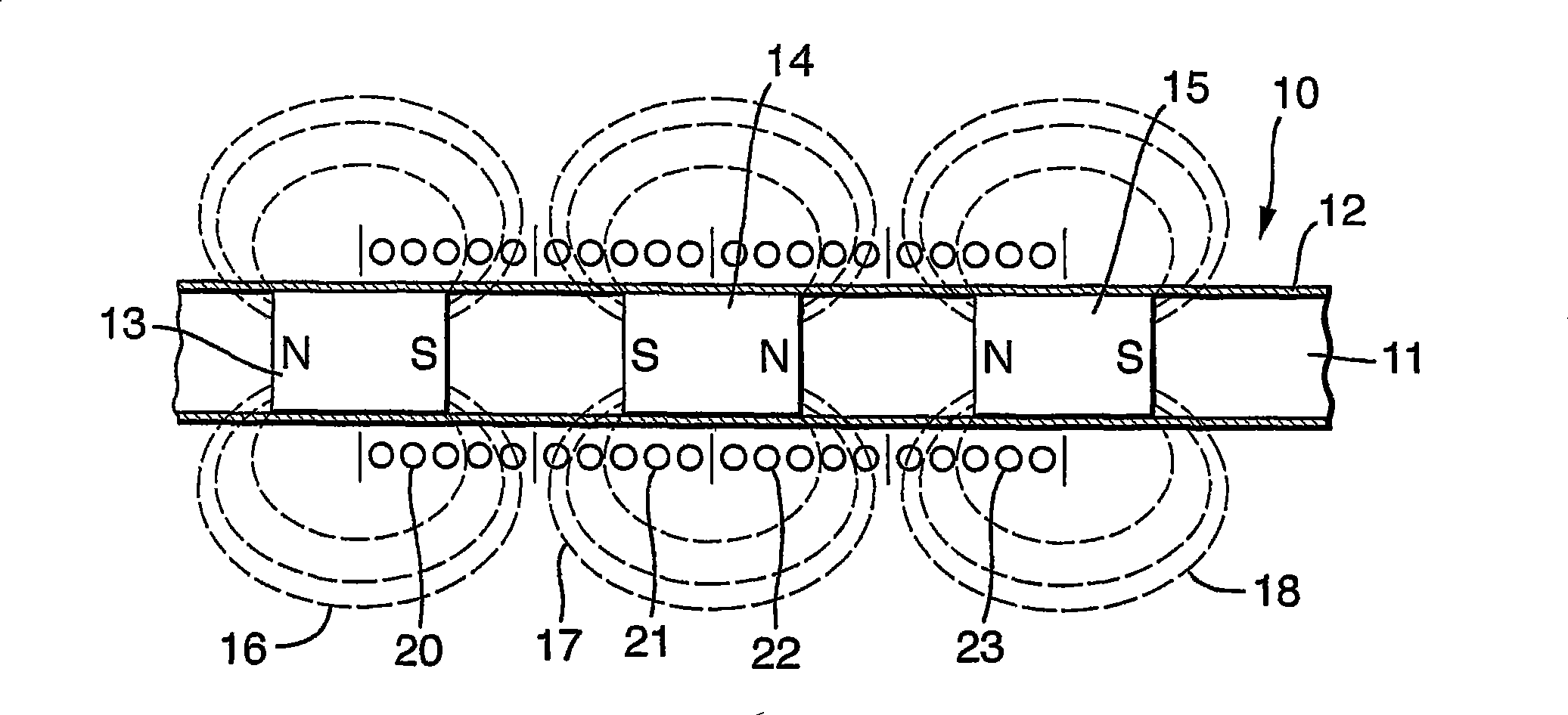
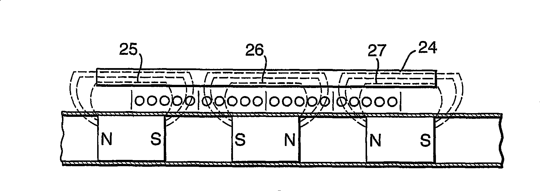
[0035] See figure 1 , an improved typical tubular linear generator disclosed herein is indicated generally by the reference numeral 10 . The converter 11 comprises a non-ferromagnetic tube 12 in which a series of magnetized permanent magnets 13, 14, 15 etc. are arranged axially at intervals. It can be seen that the like-named poles of the magnets face each other. The result is magnetic teeth as shown in 16, 17 and 18, which emanate radially from the tube supporting the permanent magnet, and the rotation of the coaxial armature coils shown can cut the magnetic teeth, here the same Shaft armature coils are indicated at 20 , 21 , 22 and 23 . (Note that these coils are fixed inside another tube, not shown here for clarity.) Forcing relative motion between the armature and converter results in sinusoidal AC power in the armat...


PUM


Abstract

A tubular linear generator comprises an elongate translator (12), containing a series of permanent magnets (13, 14....) and one or more annular coils (not shown) contained within and affixed to a ferromagnetic sleeve (31). Relative movement between the translator and armature causes the generation of electricity in the coils. The sleeve is contoured in terms of permeability around its circumference at one or both its ends, as shown at (32), in order to reduce cogging forces between the sleeve and the permanent magnets along the translator.

Description

technical field [0001] The present invention relates to improvements in the performance of tubular linear generators. Background technique [0002] The improvement of the tubular generator disclosed herein can be used in the armature of various generators comprising one or more toroidal coils and the converter comprising a series of elongated magnetic poles. A series of poles may be formed by a plurality of longitudinally arranged permanent magnets for intensive reciprocation through said toroidal coil. The magnetic flux emanating from the poles cuts the toroidal coil, generating electricity. An embodiment of such a structure is the tubular linear motor of the British patent GB2079068 and its foreign counterparts, which are widely used in the world at present. [0003] (It should be noted that in this text the word armature refers to the part contained in the generator coils and the word converter refers to the parts contained in the permanent magnets. The current flows as...

Claims


Application Information

Patent Timeline
Patent Type & Authority Patents(China)
IPC IPC(8): H02K41/03H02K35/00
CPCH02K35/00H02K7/1876H02K2213/12H02K41/031H02K49/10H02K1/145Y02E10/30
Inventor 休-彼得·格兰维尔·凯利
Owner TRIDENT ENERGY
Why Eureka
Try Eureka