
Internal Combustion Engine with Alternator

a technology of internal combustion engine and alternator, which is applied in the direction of locomotive transmission, electric generator control, electric motor propulsion transmission, etc., can solve the problems of small space available for arranging such an alternator, and the alternator in portable hand-held power tools is subject to significant mechanical loads, so as to achieve sufficient electric power, reduce mechanical and thermal loads, and reduce space

Active Publication Date: 2008-03-06
ANDREAS STIHL AG & CO KG
View PDF16 Cites 15 Cited by
  • Summary
  • Abstract
  • Description
  • Claims
  • Application Information

AI Technical Summary

Benefits of technology

[0004] It is an object of the present invention to provide an internal combustion engine with an alternator that requires little space, delivers sufficient electric power, and is resistant to mechanical and thermal loads over a long operating time.
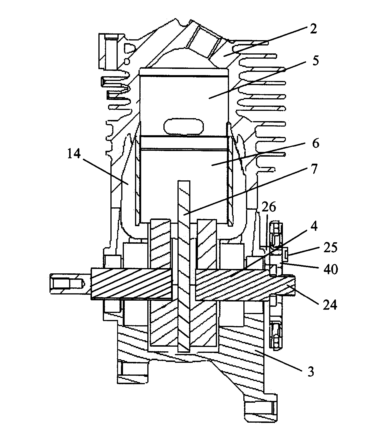
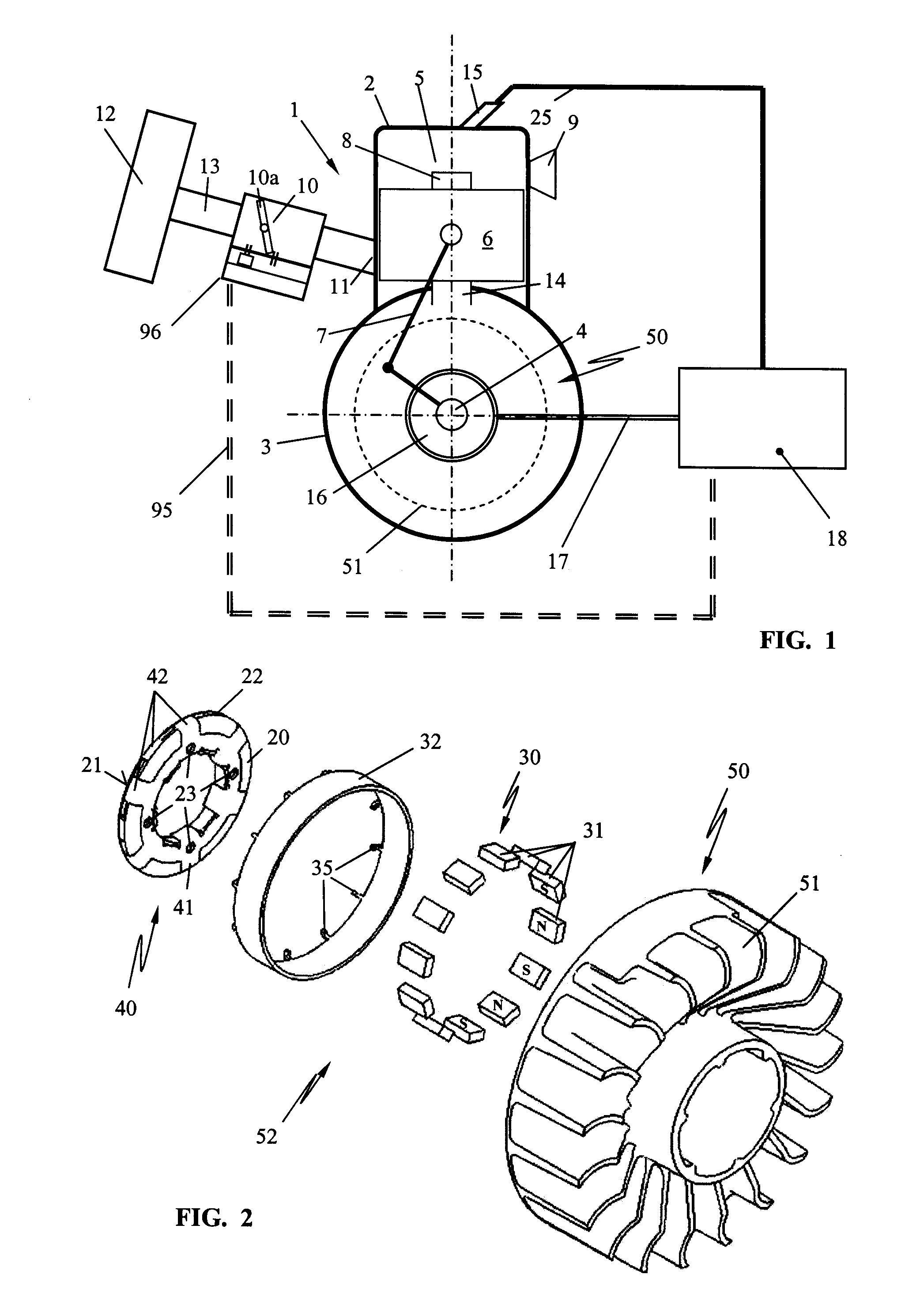
[0005] In accordance with the present invention, this is achieved in that the alternator is arranged within the radial boundary of the wheel member and external to the crankcase. In this way, the alternator can partially penetrate into the crankcase and / or into the wheel member or can be integrated therein. The stator, provided in particular with a stationary induction coil, is penetrated by the crankshaft while the rotor is fixedly connected to the wheel member. The arrangement of the alternator in the area between the crank case and the wheel member provides a mechanical protection against damage and soiling. When the crankcase is appropriately designed and the wheel member rotating with the crankshaft is appropriately modified, in the space that is thus provided the alternator can be arranged without increasing the size in the crankshaft direction significantly.
[0007] The magnets of the annular magnet arrangement (magnet ring) are positioned expediently in recesses of the wheel member itself and are advantageously secured against failing out of the recesses by gluing or clamping. In order to improve magnetic flux, the annular magnet arrangement of the rotor can have an external magnet yoke. Also, the arrangement of an individual magnet instead of an annular magnet arrangement is expedient.
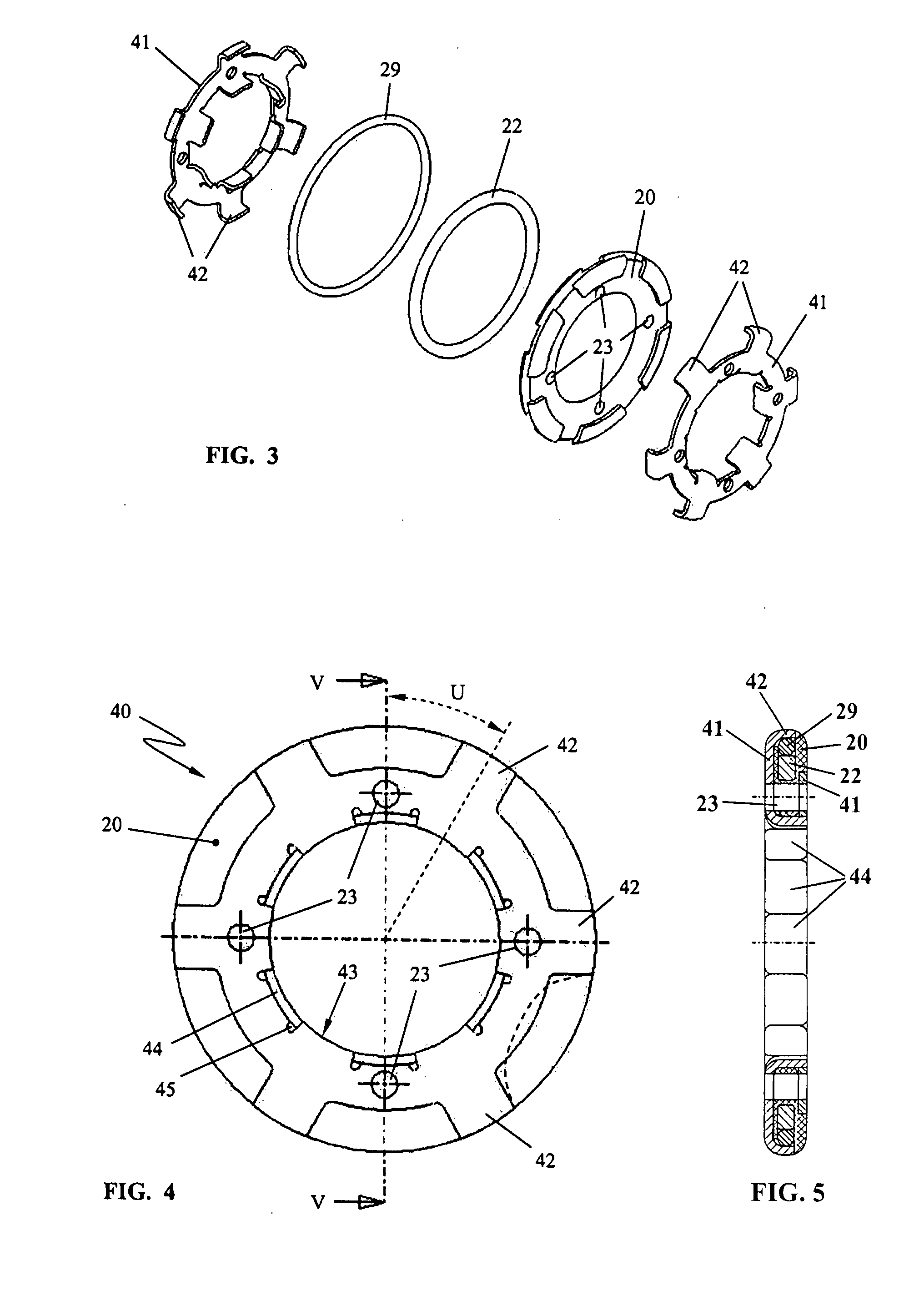
[0008] The stator is essentially formed by the coil support that is enclosed by a stator yoke having poles that are positioned at the outer periphery of the coil support. In this connection, the stator yoke is comprised of at least two sheet metal pieces of minimal thickness wherein a first sheet metal piece is arranged on a first end face of the coil support and the second sheet metal piece on the opposite end face of the coil support. The spaced-apart poles of the stator sheet metal pieces mesh like combs with one another by engaging the pole gaps, respectively, and are positioned at the outer periphery of the coil support. At the inner circumference of the coil support, the sheet metal pieces engage one another so as to conduct magnetic flux. Preferably, the stator sheet metal pieces are connected at the inner circumference of the coil support positive-lockingly or frictionally with one another and / or with the coil support for example, by a snap-on connection. In order to prevent undesirable leakage flux between the claws, the spacing between neighboring claws is greater than 2 mm, preferably greater than 3 mm. In order to provide, on the one hand, at a minimal engine speed of approximately 300 / min a satisfactory high power output and, on the other hand, to prevent at high engine speed of approximately 15,000 / min too much heat development, the stator sheet metal is selected to have a thickness of approximately 1 mm. The stator sheet metal is advantageously manufactured from electric sheet. Electric sheet has the positive property that, as a result of its high electric resistance, detrimental eddy currents are reduced and magnetic flux is still conducted well. In this way, a small-size claw pole alternator with stationary coil is provided that has high engine speed dynamics from 300 / min to 15,000 / min without becoming hot. The claw pole alternator provides power of 2 to 20 watts at low engine speed and power between 40 and approximately 200 watts at high engine speed.
[0010] In a preferred embodiment of the invention, th e alternator is not only provided as an energy source but at the same time as an ignition angle transducer. In this connection, the signals of the alternator are electronically evaluated because the alternating voltage signal contains characteristic features that allow to deduce information in regard to the angle position of the crankshaft. When a characteristic feature is recognized, the actual angle position of the crankshaft can be correlated with the corresponding crank angle of the characteristic feature so that ignition can be carried out in accordance with the crank angle without this requiring an angle sensor.

Problems solved by technology

In the housings of portable hand-held power tools, there is only little space available for arranging such an alternator.
In this connection, it must be taken into consideration that an alternator in portable hand-held power tools is subjected to significant mechanical loads, for example, caused by vibrations.

Method used


Image

  • Internal Combustion Engine with Alternator
  • Internal Combustion Engine with Alternator
  • Internal Combustion Engine with Alternator

Examples


Embodiment Construction

[0058] The schematic illustration of FIG. 1 shows an internal combustion engine 1 embodied as a two-stroke engine. The invention is however not limited to the use in single-cylinder or multi-cylinder two-stroke engines. The invention is also suitable for use in single-cylinder or multi-cylinder four-stroke engines or other engines, for example, rotary piston engines. In modern power tools such as motor chain saws, cut-off machines, trimmers, blowers or similar devices, such engines, in particular reciprocating piston engines, are used as drives.

[0059] The internal combustion engine 1 comprises a cylinder 2 with a crankcase 3, in which a crankshaft 4 is rotatably supported. A combustion chamber 5 is provided in the cylinder 2 and is delimited by a reciprocating piston 6. The piston 6 is connected by connecting rod 7 to crankshaft 4 in the crankcase 3 and drives the crankshaft 4 in rotation. In the illustrated embodiment an intake port 8 for combustion air and / or a mixture opens into...


PUM


Abstract

An internal combustion engine has a combustion chamber having a spark plug arranged thereat. A crankcase supports a crankshaft. An intake for introducing fuel and combustion air into the combustion chamber is provided. An exhaust for exhausting combustion gases from the combustion chamber is provided. A piston is connected to the crankshaft and drives the crankshaft in rotation. A wheel member is connected to the crankshaft and rotates with the crankshaft. An alternator driven by the crankshaft supplies electric power to a consumer. The alternator is arranged within a radial boundary of the wheel member and external to the crankcase. The alternator has a stator and a rotor, wherein the crankshaft penetrates the stator and wherein the rotor is fixedly connected to the wheel member.

Description

BACKGROUND OF THE INVENTION [0001] The invention relates to an internal combustion engine in a hand-held power tool such as a motor chain saw, a cut-off machine, a trimmer, a blower or a similar device, wherein the internal combustion engine comprises a piston, a combustion chamber with a spark plug, and a crankshaft driven in rotation by the piston and supported in a crankcase. An intake for combustion air and fuel and an exhaust for combustion gases are provided. A wheel member is mounted on the crankshaft and rotates with the crankshaft. An alternator is driven by the crankshaft and supplies an electric consumer. [0002] In the case of such internal combustion engines, it is known to use the alternator as an energy source for operating the ignition as well as for operating electric consumers, for example, a carburetor heater, a handle heater for a motor chain saw or the like. [0003] In the housings of portable hand-held power tools, there is only little space available for arrangi...

Claims


Application Information

Patent Timeline
Patent Type & Authority Applications(United States)
IPC IPC(8): F02N11/04B60L50/10
CPCF02B63/04F02B63/042F02N15/022F02N11/04F02D2400/06
Inventor MAIER, GEORGSCHIEBER, EBERHARDWEIMER, INAABOU-ALY, MOHAMEDLEUFEN, HEINRICH
Owner ANDREAS STIHL AG & CO KG
Learn More