
Method and apparatus for expanding and contracting graphical function displays

Active Publication Date: 2005-02-15
ADOBE INC
View PDF3 Cites 123 Cited by
  • Summary
  • Abstract
  • Description
  • Claims
  • Application Information

AI Technical Summary

Benefits of technology

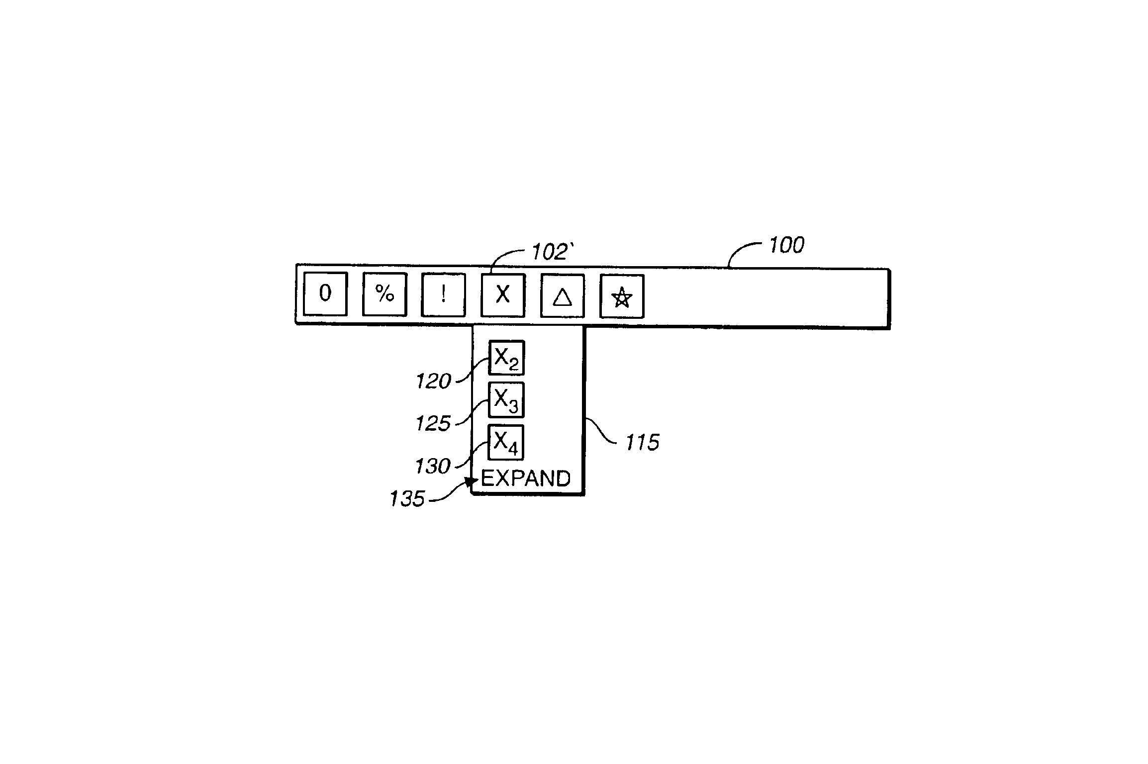
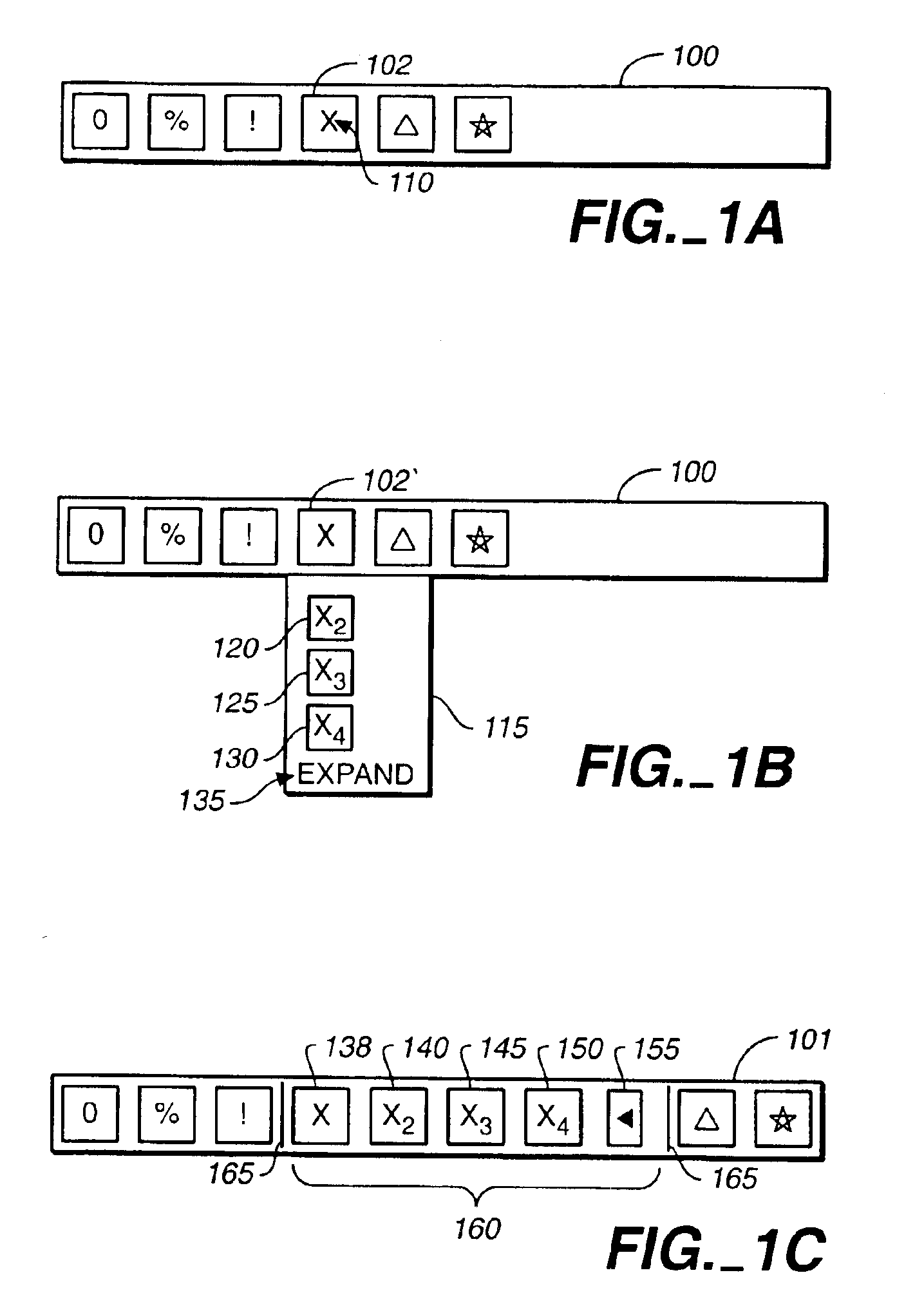
The invention can be implemented to realize one or more of the following advantages. A graphical function display, referred to herein as a toolbar, can be expanded or contracted to either display or hide groups of tools, providing a user with easy access to a group of tools while minimizing the screen space required to display the tools and providing access to the tools in a familiar and easily accessible location for the user. A user can expand a toolbar to include a plurality of icons representing a group of tools by a single click of a mouse, allowing the user to easily display only those tools required by the user and to conserve screen space. A user can also contract a toolbar, by replacing a group of icons representing a group of tools with one or more icons representing one or more tools and representing the group of tools, with minimal effort by the user, thus allowing the user to easily adapt the user's toolbar to a current task being performed by the user.

Problems solved by technology

As software programs become more complex, one of the biggest issues faced by program designers is making a software program's controls easily accessible to a user within a user interface.
As the number of controls accessible to a user grows, it can become impractical to display all such controls in a toolbar.
Floating tool palettes use valuable screen space and can create a cluttered user interface that may also be confusing to a user, particularly if a tool is represented by both an icon on the toolbar and another icon on a separate floating tool palette.

Method used


Image

  • Method and apparatus for expanding and contracting graphical function displays
  • Method and apparatus for expanding and contracting graphical function displays
  • Method and apparatus for expanding and contracting graphical function displays

Examples


Embodiment Construction

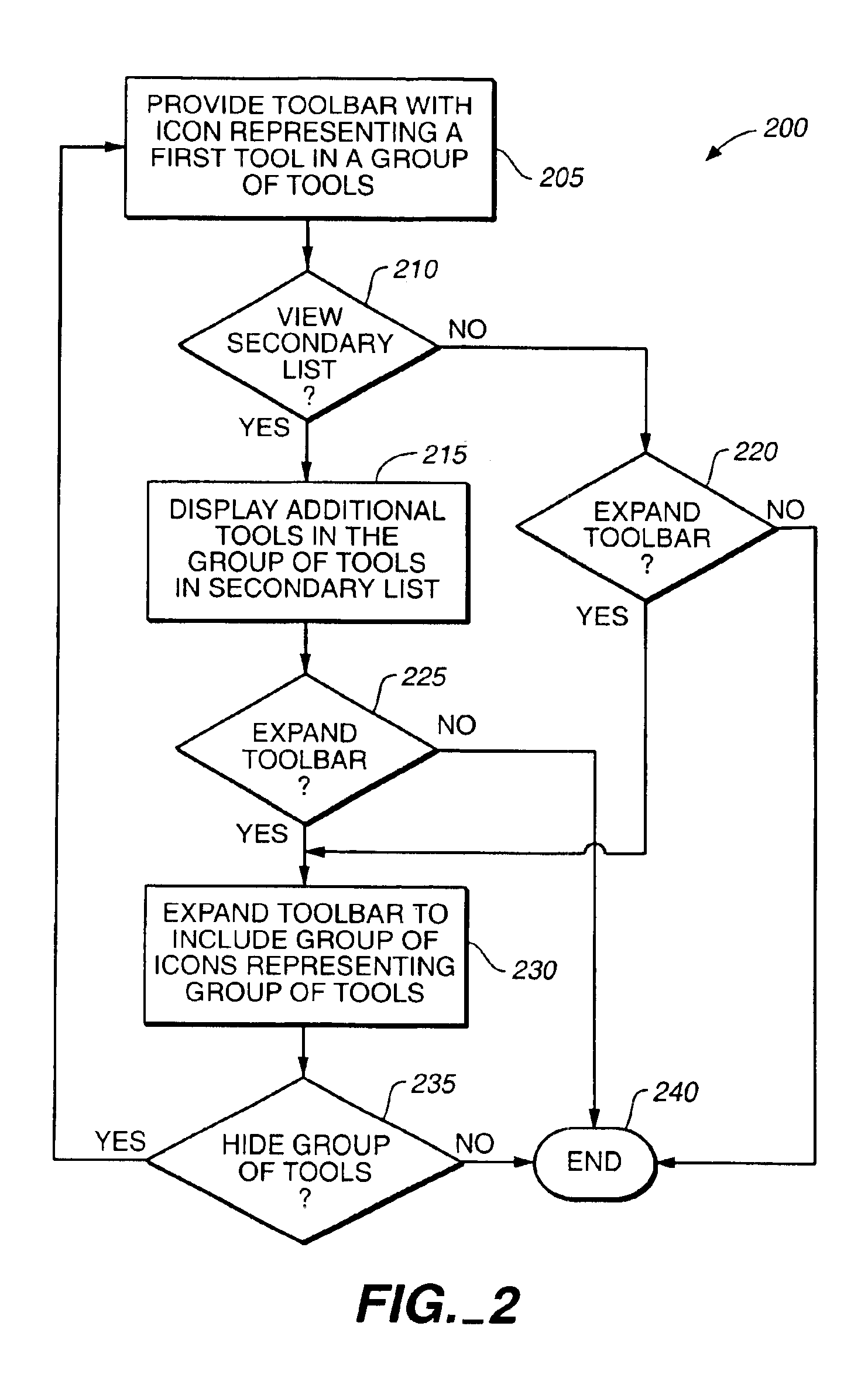
A method for expanding and contracting graphical function displays allows a user of a graphical user interface easy access to frequently used functions, while minimizing the clutter of the user interface and the space taken up by user interface elements. The graphical function display can be expanded and contracted with a single mouse click allowing the user to toggle between different variations of one expandable and contractable graphical function display with minimal effort. In general, a graphical function display can be expanded by replacing an icon representing a group of tools, or optionally representing a first tool in a group of tools and the group of tools, with a plurality of icons representing the plurality of tools in the group of tools. Similarly, a graphical function display can be contracted by replacing a plurality of icons representing tools in a group of tools with one or more icons, but less than the plurality of icons, representing one or more tools and the grou...


PUM


Abstract

Methods and apparatus, including computer program products, implementing and using techniques for customizing a graphical function display. In one aspect, the invention features operations to customize a toolbar graphically representing tools including one or more groups of tools. A tool is represented by an icon on the toolbar, and a group of tools is represented by one or more icons on the toolbar. In response to user input, an icon representing a group of tools can be replaced with all or a subset of icons representing tools in the group of tools. Similarly, in response to user input, a plurality of icons representing tools in a group of tools can be replaced with an icon representing the group of tools and can also represent a tool in the group of tools.

Description

BACKGROUND OF THE INVENTIONThis invention relates to graphical function displays for computer program applications having a graphical user interface.As software programs become more complex, one of the biggest issues faced by program designers is making a software program's controls easily accessible to a user within a user interface. Graphical function displays of program functions are commonly referred to as toolbars having icons representing program functions, also referred to as toolbar buttons. A number of other names are used to reference graphical function displays, including menu and tool palette. The generic term toolbar shall be used herein to refer to all types of graphical function displays, including menus and tool palettes. The term tool shall be used herein to refer to all types of program functions represented by graphical function displays. A tool represented by an icon can be accessed by a user, for example, by a mouse click on the icon, by highlighting the icon or...

Claims


Application Information

Patent Timeline
IPC IPC(8): G06F13/00G06F3/048
CPCG06F3/0482G06F3/04817
Inventor FOX, MARTINMCAFEE, ROBERT
Owner ADOBE INC
Learn More