Magnetically guided catheter with concentric needle port

a catheter tip and magnetic navigation technology, applied in the field of electrophysiology catheters, can solve the problems of difficult integration of catheter tip magnetic navigation, catheter tip lack of magnetic material volume for adequate magnetic navigation and control, and difficulty in adequately deflecting catheters without increasing magnetic volume, etc., to achieve optimal tissue injection success and improve maneuverability and angulation

Active Publication Date: 2009-01-15
BIOSENSE WEBSTER INC
View PDF39 Cites 127 Cited by
  • Summary
  • Abstract
  • Description
  • Claims
  • Application Information

AI Technical Summary

Benefits of technology

[0007]The present invention is directed to an electrophysiology catheter that is adapted for ablation, mapping, injection, and directional control by an external magnetic system, including a magnetic surgery system (MSS). In one embodiment, the catheter has a catheter body, an intermediate section, and a tip section having a tip electrode configured with an omnidirectional distal end and a concentric needle port. The omnidirectional distal end of the tip electrode improves maneuverability and angulation. A dome configuration enables a wide range of tissue contact angles. The concentric needle port provides optimal tissue injection success.

Problems solved by technology

While these sensors provide useful data to determine location and position of the catheter, they can be relatively large and consequently tend to occupy a significant amount of space in the catheter tip.
However, because space in the catheter tip is at a premium, the integration of ablation, mapping and injection capabilities with magnetic navigation in a catheter tip has been challenging.
While such catheters exist, the catheter tips tend to lack sufficient volume of magnetic material for adequate magnetic navigation and control and their needle ports have been generally eccentric or off-axis.
However, added stiffness tends to make it more difficult to adequately deflect the catheter without increasing magnetic volume.
Insufficient magnetic “adhesion” force would limit the ability of the needle to penetrate tissue.

Method used


Image

  • Magnetically guided catheter with concentric needle port
  • Magnetically guided catheter with concentric needle port
  • Magnetically guided catheter with concentric needle port

Examples


Embodiment Construction

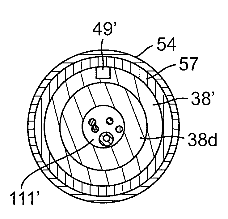
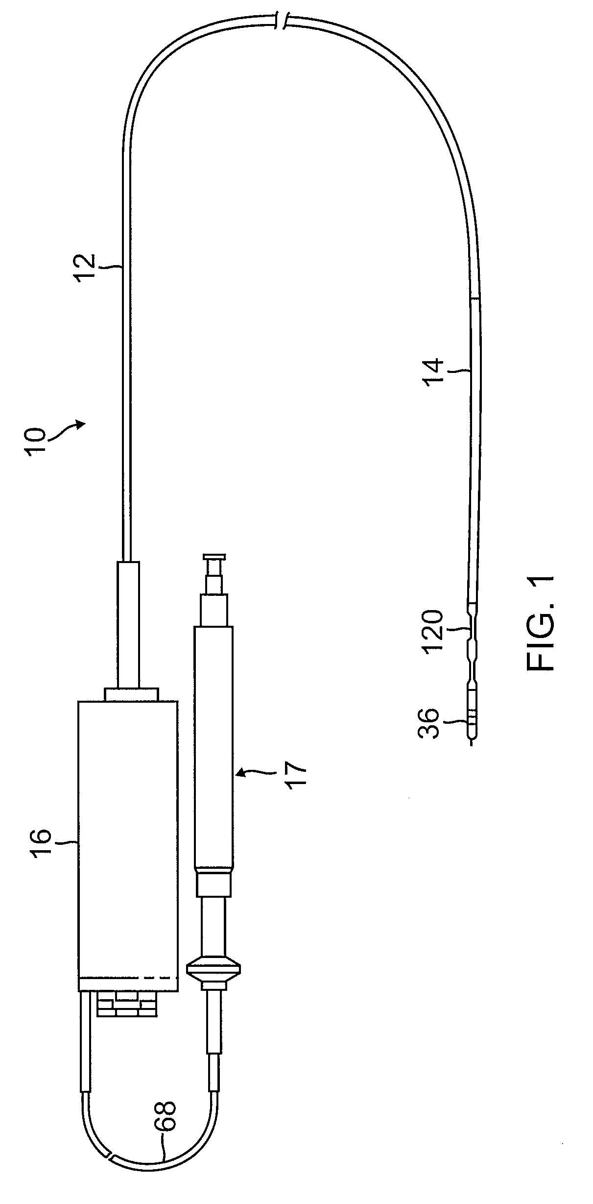
[0044]As shown in FIGS. 1-9, catheter 10 of the present invention comprises an elongated catheter body 12 having proximal and distal ends, a very soft and flexible intermediate section 14 at the distal end of the catheter body 12, a magnetically-maneuverable tip section 36 through which an injection needle 46 can be extended and retracted, a connection housing 16 at the proximal end of the catheter body and a needle control handle 17 proximal of the housing 16, by which a user can manipulate needle extension and retraction. In accordance with a feature of the invention, the tip section includes a tip electrode 37 for ablation and mapping, an electromagnetic position sensor 34 to provide location and orientation data, and a magnetic device 38 to facilitate magnetic navigation and control.

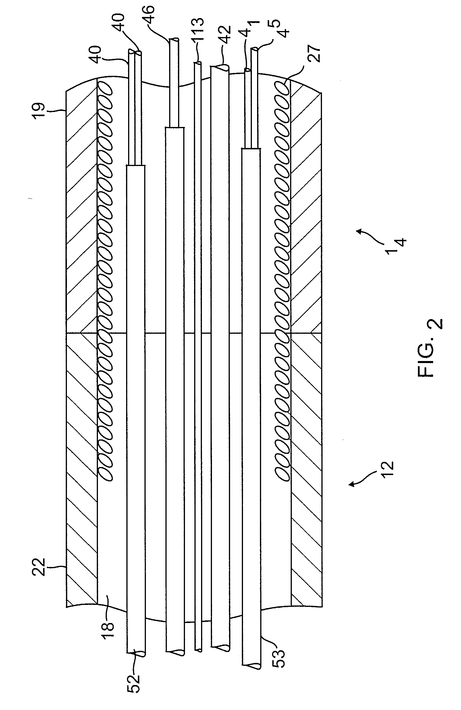
[0045]With reference to FIGS. 1 and 2, the catheter body 12 comprises an elongated tubular construction having a single, axial or central lumen 18. The catheter body 12 is flexible, i.e., bendable, b...


PUM


Abstract

A catheter adapted for ablation, mapping, injection, and directional control by an external magnetic system has a catheter body, an intermediate section, and a tip section having a tip electrode configured with an omnidirectional distal end and a concentric needle port. The tip electrode houses a magnetic device and a position sensor arranged in an integrated configuration, wherein the configuration facilitates a path in the tip section for a component, including an injection needle, to extend through the tip section for extension and retraction with reduced stress and friction. The integrated configuration is an efficient use of space in the tip electrode that allows the tip section to carry both the position sensor for determining location and orientation of the tip section and the necessary volume of magnetic or magnetizable material to accomplish magnetic navigation. The catheter also includes a very soft and flexible intermediate section and an even softer and more flexible distal transitional section carrying additional magnetic members to facilitate remote magnetic navigation.

Description

CROSS-REFERENCE TO RELATED APPLICATION(S)[0001]This application claims priority to U.S. Provisional Application No. 60 / 939,649, filed May 23, 2007, the entire disclosure of which is hereby incorporated by reference.FIELD OF INVENTION[0002]The present invention relates to electrophysiology catheters, and in particular to remote magnetic and injection catheters.BACKGROUND[0003]Electrode catheters have been in common use in medical practice for many years. They have been used to stimulate and map electrical activity in the heart and to ablate sites of aberrant electrical activity. More recently, therapeutic and diagnostic agents have been delivered into the heart, including the heart wall, through a percutaneous transluminal approach with the use of catheters. In particular, catheters with a needle have been used for injection directly into the myocardium for a variety of treatments, including myocardial revascularization. For example, U.S. Pat. No. 6,309,370 entitled Intracardiac Drug...

Claims


Application Information

Patent Timeline
Patent Type & Authority Applications(United States)
IPC IPC(8): A61M25/092
CPCA61B18/1492A61B2017/00084A61B2018/00839A61M25/0068A61M25/0069A61M25/008A61M25/0082A61M25/0084A61M2025/0089A61B34/73A61B2090/3975A61B2034/2051A61B5/062A61M25/0127A61M25/0158A61B5/283A61B5/06
Inventor BIRCHARD, CHRISTOPHER J.CREED, JERETT A.WONG, WAI CHUNG
Owner BIOSENSE WEBSTER INC
Why Eureka
Try Eureka