Electro-optical apparatus, flexible printed circuit board, manufacturing method for electro-optical apparatus, and electronic equipment

Active Publication Date: 2005-04-28
BOE TECH GRP CO LTD
View PDF13 Cites 121 Cited by
  • Summary
  • Abstract
  • Description
  • Claims
  • Application Information

AI Technical Summary

Benefits of technology

[0020] In this arrangement, since the mounted circuit board and the mounted electronic components are prevented from protruding from the outline of the flexible printed circuit board in a bent state by mounting the circuit board on which the electronic components are mounted inside the flexible printed circuit board bent toward the light source unit, a space-saving electro-optical apparatus is obtained.
[0021] I

Problems solved by technology

However, when mounting the plurality of electronic components on the flexible FPC using the aforementioned mounting method in the related art, there is a problem in that a significantly long time is required for mounting the electronic components, and hence workability is bad.
In addition, there are

Method used


Image

  • Electro-optical apparatus, flexible printed circuit board, manufacturing method for electro-optical apparatus, and electronic equipment
  • Electro-optical apparatus, flexible printed circuit board, manufacturing method for electro-optical apparatus, and electronic equipment
  • Electro-optical apparatus, flexible printed circuit board, manufacturing method for electro-optical apparatus, and electronic equipment

Examples


first embodiment

[0065] First Embodiment

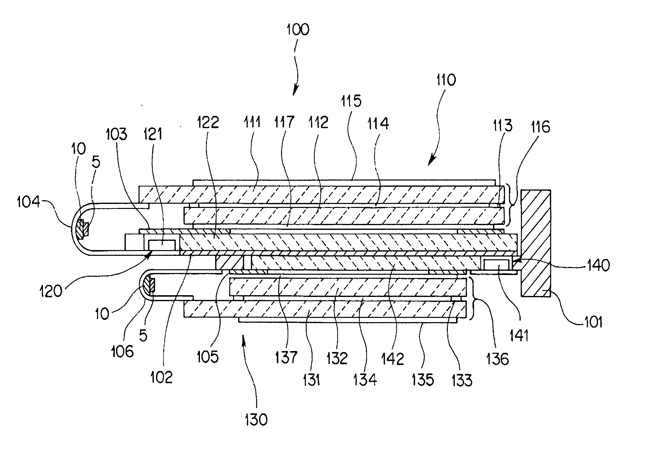
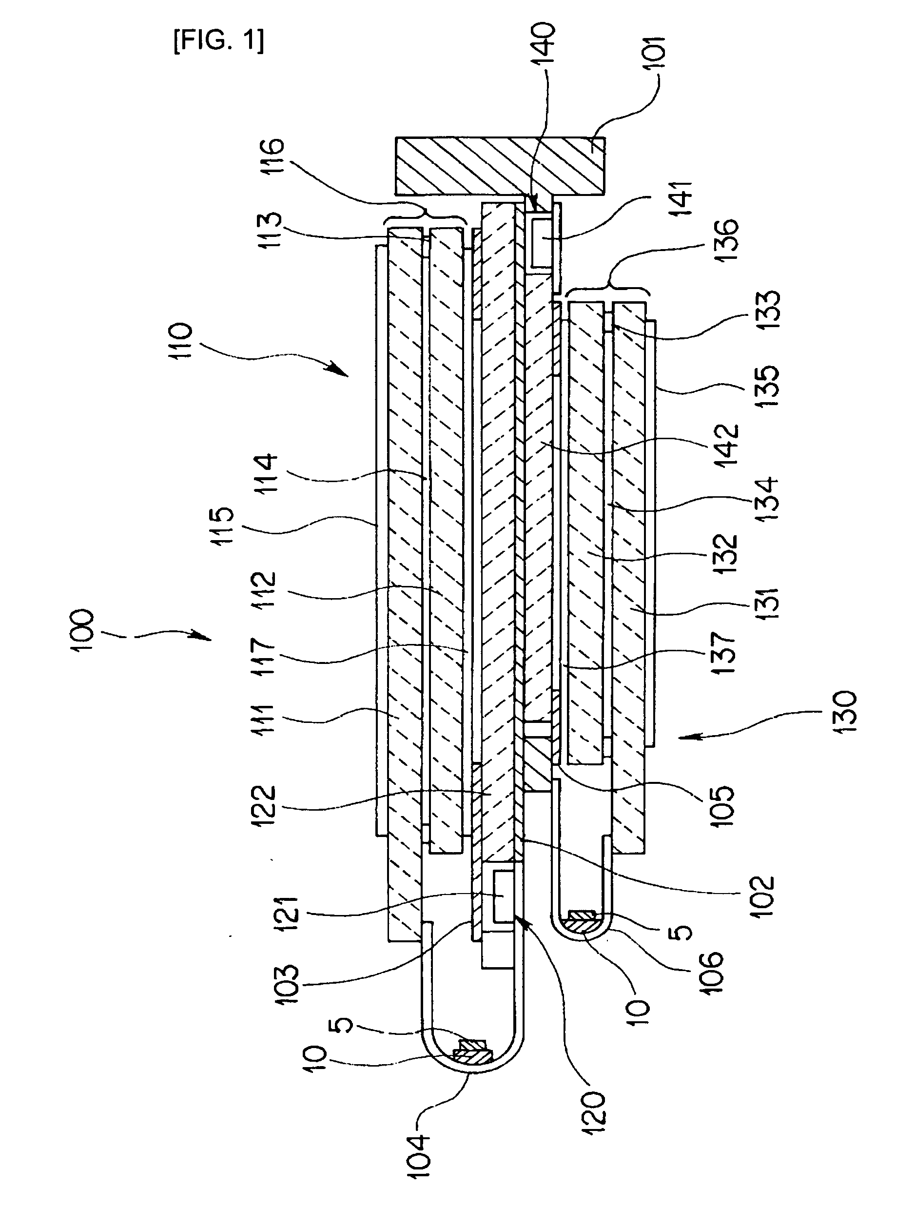
[0066]FIG. 1 is a cross-sectional view showing a liquid crystal display device according to an embodiment of the present invention. In the description, a surface on the upper side of the drawing is designated as a front surface, and a surface on the lower side of the drawing is designated as a back surface for convenience of explanation.

[0067] As shown in FIG. 1, a liquid crystal display device 100 as an electro-optical apparatus is a so-called back surface integrated liquid crystal display device including a first liquid crystal display module 110 and a second liquid crystal display module 130 as principal components.

[0068] The first liquid crystal display module 110 includes a first liquid crystal display panel 116 as an electro-optical panel having a display section, an FPC (flexible printed circuit) board 104 electrically connected to the first liquid crystal display panel 116, a circuit board 10 on which an electronic component 5 is mounted, and a backl...

modification 1

[0155] Modification 1

[0156] The liquid crystal display module 110 of the liquid crystal display device 100, which corresponds to the electro-optical apparatus, may have a structure in which the liquid crystal display panel 116 and the FPC 104 connected thereto are fixed in the case 101 as a supporting member, and a space in which the backlight unit 120 can be assembled by inserting from behind is provided in the case 101. In this arrangement, assembly of the backlight unit 20 can be performed relatively easily. Also, even when there are problems in the backlight unit 120 in the course of the module assembling process, replacement can be performed relatively easily.

modification 2

[0157] Modification 2

[0158] The number of circuit boards 10 is not limited to one. By mounting the circuit components which is subject to generation of noise due to the structure of the circuit on the additional circuit board and changing the place for installation, effect of the noise can be prevented.

[0159] Technological ideas grasped from the above-described embodiment and the modifications are as follows.

[0160] An electro-optical apparatus including an electro-optical panel having a display unit, a flexible printed circuit board having a output terminal to be electrically connected to at least one terminal section of the above described electro-optical panel, and a circuit board on which all or part of a plurality of electronic components for driving the electro-optical panel are mounted, wherein the circuit board is electrically connected to the flexible printed circuit board.

[0161] An electro-optical apparatus including an electro-optical panel having a display unit, a flex...


PUM


Abstract

A liquid crystal display device includes a liquid crystal display panel having a first substrate and a second substrate opposed thereto arranged so that the inner surfaces thereof oppose each other with an intermediate sealing member and a liquid crystal interposed in the internal space, and a flexible printed circuit board having an input/output terminals connected thereto. A circuit board on which a plurality of electronic components required for operating the liquid crystal display apparatus are mounted on the flexible printed circuit board.

Description

RELATED APPLICATIONS [0001] This application claims priority to Japanese Patent Application Nos. 2003-327992 filed Sep. 19, 2003 and 2004-182455 filed Jun. 21, 2004 which are hereby expressly incorporated by reference herein in their entirety. BACKGROUND [0002] 1. Technical Field [0003] The present invention relates to an electro-optical apparatus, a flexible printed circuit board, a manufacturing method for an electro-optical apparatus, and electronic equipment. [0004] 2. Background Art [0005] A principal portion of an electro-optical apparatus used as a display of electronic devices such as a mobile phone includes an electro-optical panel having an image display section using liquid crystal or the like as electro-optical material and being constituted of a plurality of picture elements, a drive circuit unit including electronic components required for driving the image display section, a flexible printed circuit (hereinafter, referred to as FPC) board for connecting electro-optica...

Claims


Application Information

Patent Timeline
IPC IPC(8): G02F1/1333G02F1/13G02F1/13357G02F1/1345G09F9/00H05K1/14H05K3/36
CPCG02F1/133615G02F1/13452H05K1/141H05K2201/055H05K3/361H05K2201/045H05K1/147G02F1/1345
Inventor YUMOTO, MASANORIHIRANO, YOSHIHISAIMAEDA, CHIAKI
Owner BOE TECH GRP CO LTD
Why Eureka
Try Eureka