Optical system for projecting device

A projection device and optical system technology, applied in the direction of optics, projection devices, optical components, etc., can solve the problems of unstable discharge arc, achieve the effects of stable discharge arc, solve flicker phenomenon, and suppress melting deformation

Inactive Publication Date: 2010-06-16
USHIO DENKI KK
View PDF6 Cites 0 Cited by
  • Summary
  • Abstract
  • Description
  • Claims
  • Application Information

AI Technical Summary

Problems solved by technology

Therefore, it is considered that when the protrusion 112C is molten and deformed, the discharge arc formed between the electrode main body portions 112B becomes unstable, causing the above-mentioned flickering phenomenon.

Method used


Image

  • Optical system for projecting device
  • Optical system for projecting device
  • Optical system for projecting device

Examples


experiment example 1

[0064] Hereinafter, a first experimental example performed to confirm the effects of the present invention will be described.

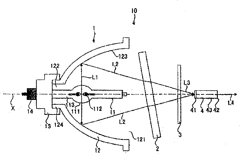
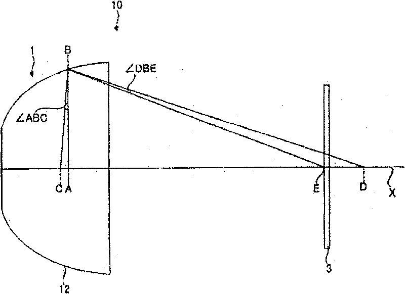
[0065] according to figure 1 With the structure shown, an optical system for a projection device according to an embodiment of the present invention was produced. In this optical system for a projection device, the center position between the electrodes of the discharge lamp is defined as A, and the intersection point where a straight line drawn from the center position A between the electrodes in a direction perpendicular to the optical axis X intersects the elliptical reflector Set as B, set the first focal point of the elliptical reflector as C, set the second focus of the elliptical reflector as D, and set the intersection of the optical axis X and the color wheel as E, so that the connection A and The value of the angle ABC (θ1) formed by the straight line of B and the two straight lines connecting the straight lines of B and C, and the angle D...

Embodiment 2

[0075] Hereinafter, a second experimental example performed to confirm the effects of the present invention will be described. Make 10 each of 6 kinds of projection device optical systems (embodiments 1 to 6), a total of 60 (these projection device optical systems have the same structure and specifications as in embodiment 1 except for the angle DBE (θ3). ). The optical systems for projection devices of Examples 1 to 6 are shown in Table 1 below. The values ​​of θ1 are all 0.396, but the values ​​of θ3 are different, being 0.05, 0.12, 0.30, 0.52, 0.57, and 0.84, respectively.

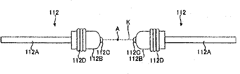
[0076] With regard to the optical systems for projection devices of Examples 1 to 6, after the discharge lamp 11 was turned on for a predetermined time, it was visually checked whether or not the protrusion 112C provided on the electrode 112 was melted and deformed. The results are shown in Table 1.

[0077] Table 1

[0078]

θ1[deg]

θ3[deg]

θ3 / θ1

electrode melting

Exam...


PUM


Abstract

The invention is to provide a projection device optical system which can prevent the blinking in the projection device which is caused by the instability of the electrical arc although the accumulatedlighting time of the electric discharge lamp loaded on the projection optical system, and the image with high quality can be provided. The projection device optical system of the invention comprisesa light source and a color wheel, the light source is composed of an electric discharge lamp and a reflecting mirror, one pair of electrodes which are arranged in the luminous tube in the electric discharge lamp respectively comprises an electrode body part and a protruding part that is arranged at the front end side of the electrode body part, the reflecting mirror reflects the light radiated bythe electric discharge lamp and the color wheel respectively separates the color of the incident color into the light comprising wavelength of R(red), green(G) and blue(B), in the cut section plane including the plane of the light axis the intermediate position between the electrodes are set to (A), the intersection point crossed by the line which is leaded out from the intermediate position (A) to the direction perpendicular to the light axis is set to (B), the first focus of the reflecting mirror is set to (C), the second focus of the reflecting mirror is set to (D), the intersection point crossed by the light axis and the color filter of the color wheel is set to (E), the angle ABC which is formed by a line (AB) which connects (A) and (B) and the line (BC) that connects (B) and (C) is set to theta1, and the angle DBE which is formed by a line (BD) which connects (B) and (D) and the line (BE) that connects (B) and (E) is set to theta 3, the light source and the color wheel are configured with a mode that satisfies the position relationship: 0.30<=theta3 / theta1<=1.31.

Description

technical field [0001] The present invention relates to an optical system for a projection device including a color wheel for separating the color of light incident from a light source into light having at least wavelengths of R (red), G (green), and B (blue). Background technique [0002] For example, projection devices typified by projection projectors are widely used for presentations such as movie theater screenings and conferences. In recent years, consumers have strongly demanded miniaturization of projection projectors due to the desire to enjoy watching movies on a large screen at home and the need to utilize the projector in small meetings held by a small number of people. [0003] According to the digital light processing (DLP; DLP is a registered trademark of Texas Instruments) system using a digital micromirror device (DMD), the illumination optical system can be easily configured, so that the projector can be miniaturized. Therefore, in recent years, projectors...

Claims


Application Information

Patent Timeline
Patent Type & Authority Patents(China)
IPC IPC(8): G03B21/20G02B7/00G03B21/14
Inventor 东间崇宽中山胜之藤井裕之伊藤尚
Owner USHIO DENKI KK
Why Eureka
Try Eureka