
Discharge lamp lighting method and discharge lamp lighting apparatus

A discharge lamp and equipment technology, applied in the field of discharge lamp lighting equipment, can solve problems such as complex circuit structure, achieve the effect of simplifying the circuit structure and prolonging the service life

Inactive Publication Date: 2007-04-11
TDK CORPARATION
View PDF2 Cites 0 Cited by
  • Summary
  • Abstract
  • Description
  • Claims
  • Application Information

AI Technical Summary

Problems solved by technology

Therefore, circuits used to generate current pulses must implement advanced timing management functions, which require complex circuit structures

Method used


Image

  • Discharge lamp lighting method and discharge lamp lighting apparatus
  • Discharge lamp lighting method and discharge lamp lighting apparatus
  • Discharge lamp lighting method and discharge lamp lighting apparatus

Examples


Embodiment Construction

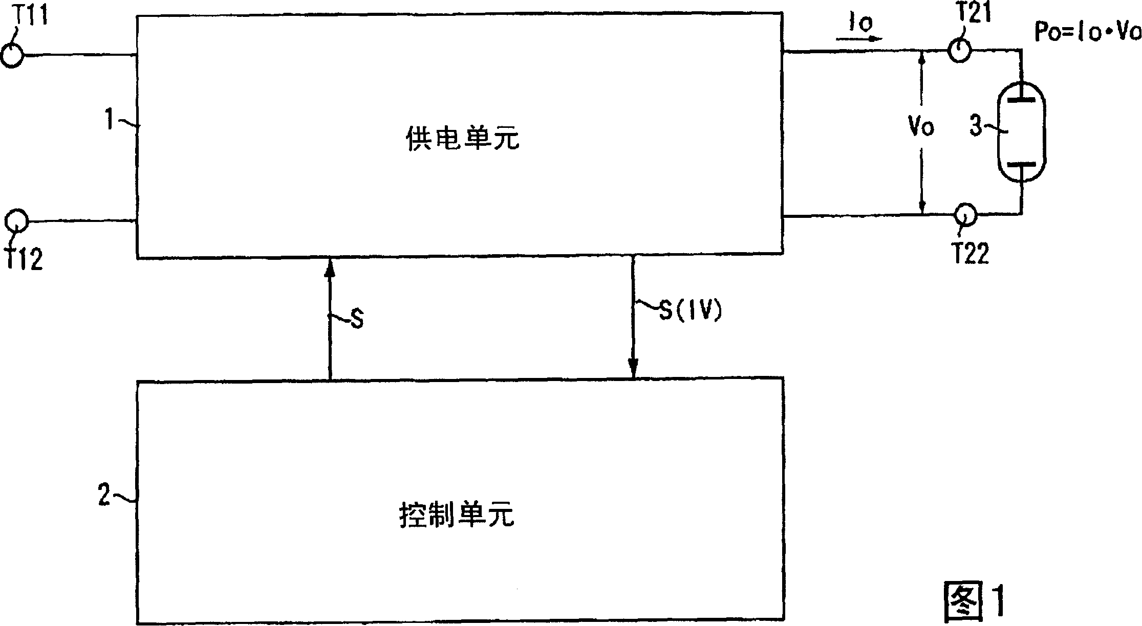
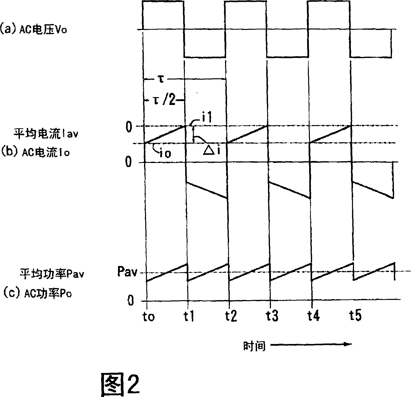
[0022] Fig. 1 is a block diagram of a structure employed in a discharge lamp lighting apparatus according to the present invention. The discharge lamp lighting device in this figure includes a power supply unit 1 and a control unit 2 . The power supply unit 1 supplies AC power (Po) to the discharge lamp 3 . DC power is normally supplied to the input terminals ( T11 ) and ( T12 ) of the power supply unit 1 . The power supply unit 1 converts this DC power into AC power at its internal power conversion circuit and supplies the resulting AC power to output terminals ( T21 ) and ( T22 ). The discharge lamp 3 whose both ends are connected to the output terminals ( T21 ) and ( T22 ) receives AC power (Po) supplied from the output terminals ( T21 ) and ( T22 ). If the power supply unit 1 is provided on its input side with a power conversion circuit for converting AC to DC, AC power can be input to the input terminals ( T11 ) and ( T12 ).

[0023] Figure 2 (a) shows the waveform of ...


PUM


Abstract

The present invention relates to a discharge lamp lighting method and a discharge lamp lighting apparatus that achieve a reduction in the extent of lamp flickering by adopting a relatively simple circuit structure. A power supply unit 1 supplies AC power (Po) to a discharge lamp 3, and a control unit 2 implements control on the power supply unit 1 so as to gradually increase the instantaneous value of the AC power (Po) during a half cycle (tau / 2) of an AC pulse current (Io) as the time elapses from the rise of the half cycle (tau / 2) toward an end of the half cycle.

Description

technical field [0001] The present invention relates to a discharge lamp lighting method and a discharge lamp lighting apparatus suitable for lighting a discharge lamp by supplying AC power to the discharge lamp. More specifically, it relates to a discharge lamp lighting method and a discharge lamp lighting apparatus ideal for applications in which a high-pressure discharge lamp, a high-pressure mercury lamp, or an ultra-high pressure mercury lamp is driven by AC power. Background technique [0002] It is known that high pressure discharge lamps can be driven relatively efficiently by supplying them with low frequency AC power at a frequency of, for example, about 50-500 Hz, as disclosed in US Pat. No. 4,485,434 and the like. [0003] However, when the high-pressure discharge lamp is lit by applying AC power, depending on the electrode temperature of the high-pressure discharge lamp and the state of the electrode surface, the position where the discharge arc is generated on ...

Claims


Application Information

Patent Timeline
IPC IPC(8): H05B41/231H05B41/16H05B41/288H05B41/292
CPCH05B41/2888Y02B20/208H05B41/2928Y02B20/202Y10S315/05Y02B20/00
Inventor 高桥透石原丰
Owner TDK CORPARATION
Learn More